

PEEK (Polyether Ether Ketone) is the ultra-high-performance thermoplastic engineering plastic currently available on the market that comes closest to being a “perfect material.” From semiconductor process chambers and aerospace engine components to spinal fusion devices and petrochemical plant seals, PEEK is found in some of the most demanding industrial applications. However, the cost of selecting the wrong PEEK grade is extremely high—a single seal made from the wrong grade could cause a plant shutdown, while an orthopedic implant that lacks medical-grade certification could result in legal liability. This guide will consolidate all the necessary information in one place Grade Selection Matrix, Chemical Compatibility Restrictions, CNC Machining SOP, Competitor Comparison, and FAQs, helping engineers and procurement professionals make the most accurate decisions.
Chapter 1: What Is PEEK? From Molecular Structure to Key Advantages
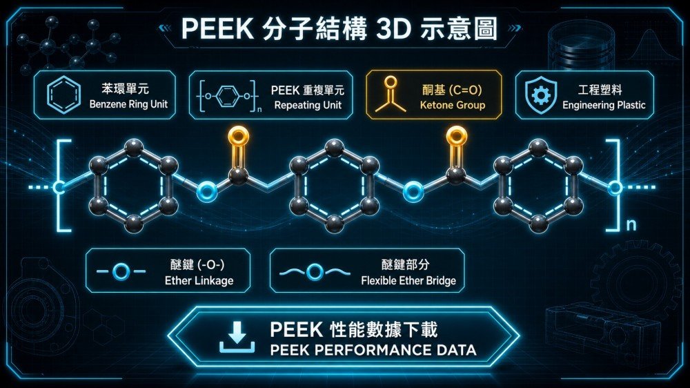
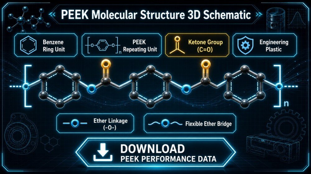
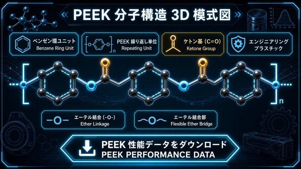
Chemical Structure: The Golden Ratio of “2 Ethers, 1 Ketone”
PEEK belongs to the polyaryletherketone (PAEK) family, and its repeating unit consists of 2 ether groups (-O-) and 1 ketone group (C=O) alternating units. This unique “2:1 ether-to-ketone ratio” gives PEEK two key properties:
- Ether group (ether bond): Provides chain flexibility and excellent chemical resistance—the electron cloud density is uniformly distributed throughout the main chain, making it difficult for most acids, bases, and organic solvents to attack the polymer backbone
- Ketone group (carbonyl group): Provides molecular chain rigidity and heat resistance, enabling PEEK to reach a melting point of 343°C, with a glass transition temperature (Tg) of 143°C
PEEK’s semi-crystalline structure (with a crystallinity of approximately 30–35%) gives it both the high stiffness and strength of crystalline regions and the toughness of amorphous regions—which is the fundamental reason why its mechanical properties far exceed those of comparable thermoplastic materials.
Overview of the Five Core Features
| Performance Indicators | Value | Meaning |
| Melting Point | 343°C | Withstands high-pressure steam sterilization (121°C–134°C) with a substantial safety margin |
| Continuous Operating Temperature (Long-Term) | 250°C | Surpasses 99% thermoplastic materials, second only to fluorinated materials such as PTFE |
| Tensile Strength (Pure) | 132–148 MPa | It is roughly two-thirds as strong as 6061 aluminum alloy, yet its density is only half that of aluminum. |
| Yang Modulus | 3.6 GPa | Close to that of human cortical bone (14–20 GPa), but far lower than that of titanium alloy (110 GPa) |
| Water absorption rate | < 0.5% | Significantly lower than PA (nylon), which ranges from 1.5% to 3%, and offers excellent dimensional stability |
Chapter 2: The Five-Tier Selection Decision Matrix—Find Your PEEK in 60 Seconds
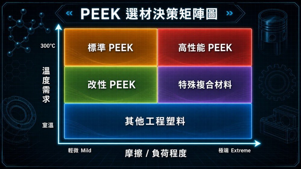
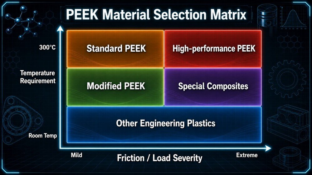
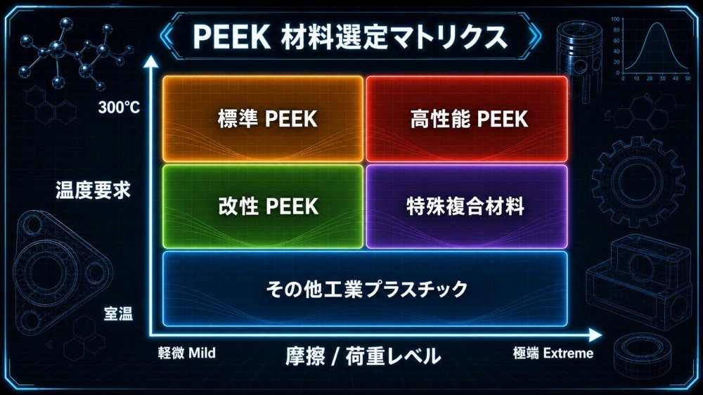
The most common mistake in selecting PEEK is not choosing the wrong material, but ratherChoosing the right material but the wrong grade for the wrong application. The following matrix consolidates the five most commonly used classifications in the industry and lists the most critical “prohibited scenarios.”
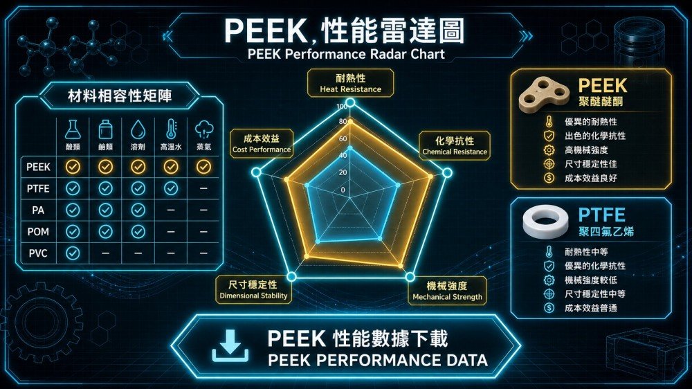
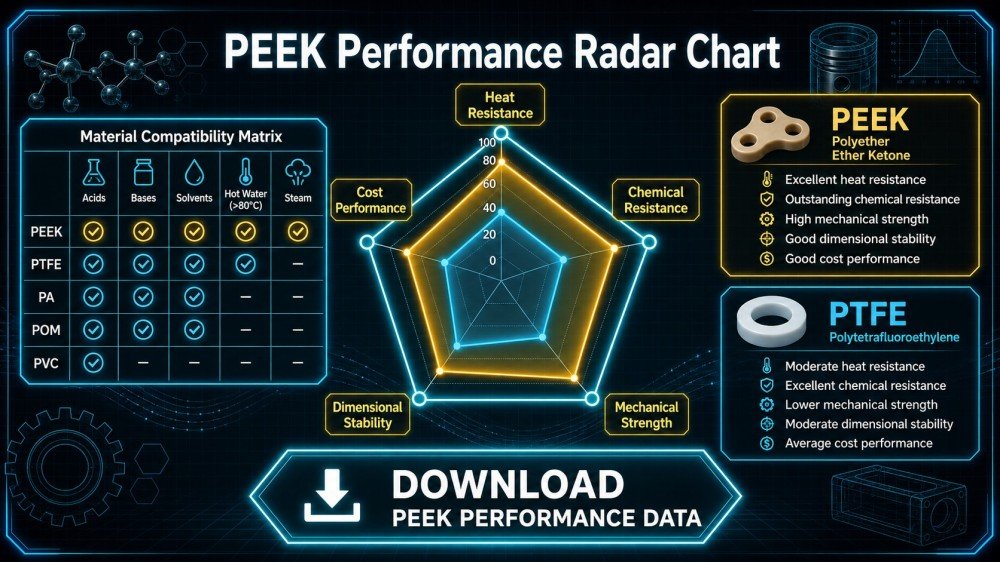
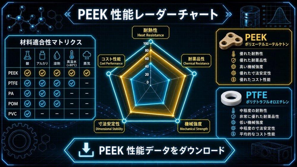
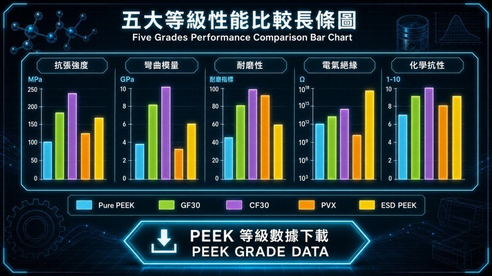
Five Levels × Application Scenario Selection Matrix
| Level | Additives | Core Strengths | Typical Scenarios | ⛔ Prohibited Scenarios |
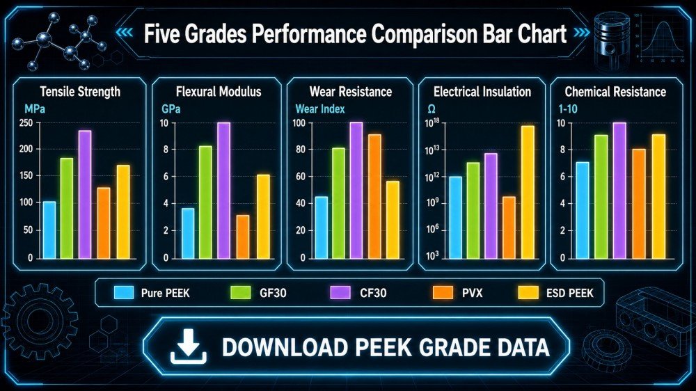
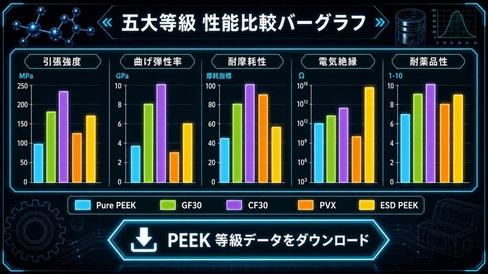
| Pure PEEK (Pure Material) | 無 | Best electrical insulation, broadest chemical compatibility, X-ray transparency, and highest compliance with food and medical standards | Semiconductor wafer fixtures, electrical insulation components, initial validation samples | ❌ Not suitable for applications involving high-load sliding wear (lacks self-lubricating properties) |
| PEEK GF30 (Glass Fiber 30%) | 30% Fiberglass | Significant improvements in rigidity (modulus of bending +50%), creep resistance, and dimensional stability | Structural components, electronic connectors, pressure vessels for oil and gas equipment | ❌ Decreased Electrical Insulation; ❌ Not suitable for medical applications requiring X-ray transmission |
| PEEK CF30 (Carbon Fiber 30%) | 30% Carbon Fiber | Highest tensile strength, lowest wear rate, improved thermal conductivity | High-load bearings, aircraft structural components, race car engine parts, high-pressure seals | ❌ Conductive; must not be used in electrical insulation components |
| PEEK PVX (HPV Bearing Grade) | 10% PTFE + Graphite + Carbon Fiber | Lowest coefficient of friction (no external lubrication required), excellent PV value | Self-lubricating bearings, slip rings, wear-resistant seal rings, pump impellers | ❌ The static seal's pressure-bearing capacity is lower than CF30 |
| ESD PEEK (Electrostatic Discharge Grade) | Carbon Black / Carbon Nanotubes | Surface resistance: 10⁴–10⁷ Ω/sq; precise electrostatic dissipation | Semiconductor equipment wafer clamps, IC test fixtures, cleanroom components | ❌ Conductive fillers affect X-ray transmissivity; ❌ Cost is significantly higher than that of Pure PEEK |
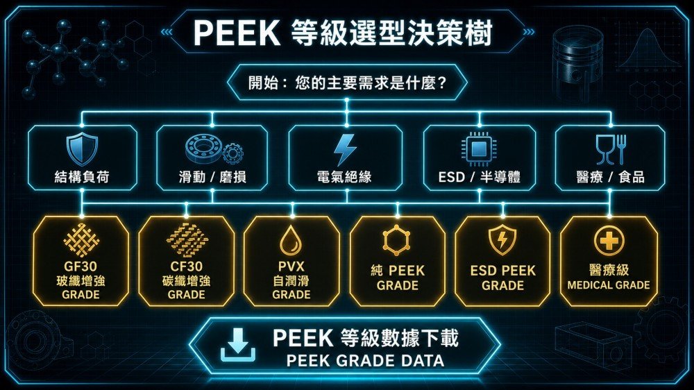
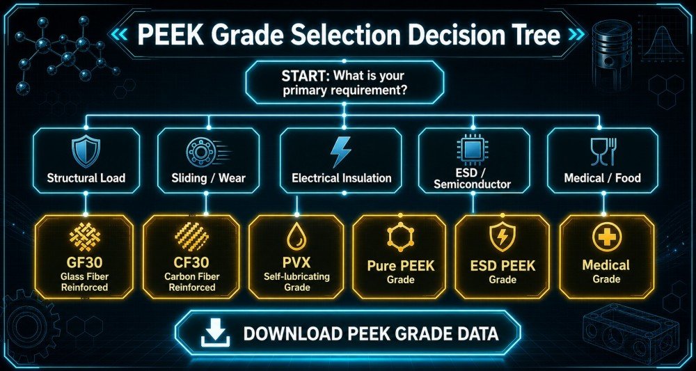
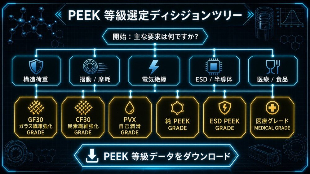
Quick Selection Guidelines
Break down the requirements into three dimensions:
- Environment(Temperature / Chemical Media / Cleanliness Level)
- Features(Load-bearing / Wear-resistant / Electrical insulation / Electrostatic dissipation)
- Compliance(Food-grade / Medical implant-grade / Semiconductor cleanroom standards)
Corresponding grades based on the intersection of the three dimensions: Typically, the process begins with validation using Pure PEEK test specimens and gradually iterates toward specialized grades, resulting in the lowest risk and most controllable costs.
Chapter 3: A Comprehensive Guide to Chemical Compatibility—"Resistant to All Chemicals" Is the Most Dangerous Misconception
PEEK does indeed have extremely broad chemical compatibility and can withstand most acids, alkalis, solvents, and oils. However, “withstanding most” does not mean “invincible”—there are three types of media that can breach PEEK’s defenses:
Three Major Chemical Compatibility Restrictions
Restricted Area 1: Highly Concentrated, Strongly Oxidizing Acids
High-concentration **sulfuric acid (>96%)**與Nitric acid (>50%)** can directly attack the polymer backbone of PEEK, causing molecular chain breakage and material degradation. The risk increases dramatically with rising temperature—while only minor surface erosion may occur at room temperature, complete failure can result within a few hours at temperatures above 80°C. Recommended alternative: Switch to PTFE 或 PFA such as perfluorinated materials.
Restricted Area 2: Specific Organic Solvents (Swelling Agents)
DMSO (dimethyl sulfoxide)、THF (tetrahydrofuran)、Dichloromethane (DCM)、Chloroform These solvents can penetrate the amorphous regions of PEEK, causing volumetric expansion (swelling) and a decline in mechanical properties. Brief exposure has limited effects, but prolonged immersion—especially at high temperatures—can result in irreversible dimensional changes and a loss of strength.
Pitfall #3: The Cumulative Effect of Conditions (The Most Easily Overlooked Trap)
"Compatibility with a single medium at room temperature" does not mean "compatibility even under conditions of high temperature, high concentration, and prolonged immersion."For every 10°C increase in temperature, the rate of a chemical reaction approximately doubles.—A combination that was originally “barely compatible” may deteriorate rapidly when multiple conditions are combined. Practical recommendation: For all severe operating conditions, always request actual TDS test data from the supplier that is specific to the combination of medium, temperature, and concentration.
Chapter 4: SOP for Error Prevention in PEEK CNC Machining
The cost of processing errors with PEEK is 10 to 100 times higher than that of general-purpose engineering plastics. The following six steps are the core SOP for reducing the scrap rate:
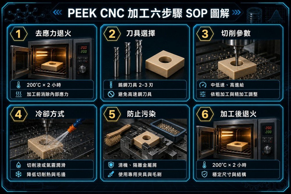

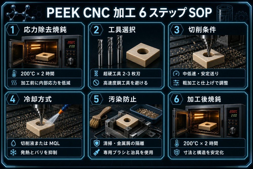
Step 1: Pre-machining annealing (to relieve residual stress)
Residual stresses develop in PEEK rods or sheets during the manufacturing process due to rapid cooling. If machined directly, the cutting forces will release these residual stresses, causing the parts to continue deforming after machining and resulting in dimensional deviations.
Annealing Conditions: Place the PEEK workpiece in the oven at Hold at 200°C for 4 hours, then slowly cool to room temperature (cooling rate ≤ 2°C/minute).
Step 2: Selecting the Right Tool
- Recommended for useCarbide Cutting Tools或Diamond-Like Carbon (DLC) Coated Cutting Tools
- Avoid using high-speed steel (HSS) cutting tools—they are prone to wear under the cutting heat generated by PEEK and may contaminate the workpiece surface.
- Carbon fiber-filled grades such as CF30 are highly wear-resistant,The tool wear rate is 3 to 5 times faster than that of the pure material., requiring more frequent blade changes
Step 3: Quick Reference Table for Cutting Parameters
| Processing Methods | Level | Cutting Speed | Feed Rate | Cutting Depth |
| Milling | Pure PEEK | 150–300 m/min | 0.05–0.15 mm/tooth | 0.5–2.0 mm |
| Milling | GF30 / CF30 | 100–200 m/min | 0.03–0.10 mm/tooth | 0.3–1.5 mm |
| Turning | Pure PEEK | 200–400 m/min | 0.10–0.30 mm/rev | — |
| Turning | GF30 / CF30 | 100–250 m/min | 0.05–0.20 mm/rev | — |
Core Principles: PEEK has extremely poor thermal conductivity (approximately 0.25 W/m·K, about 1/800th that of aluminum alloy), causing heat to concentrate at the cutting edge. The following should be used: “Slower speed + higher feed rate"This combination allows the chips to carry away the heat."
Step 4: Cooling Method
- Compressed Air Purge: The most common method, which removes chips while preventing secondary cutting
- Mist Cooling: Suitable for precision machining
- ❌ Do Not Use Oil-Based Cutting Fluids: Mineral oil may not be fully compatible with certain PEEK grades, and oil residues can be difficult to clean off.
Step 5: SOP for Contamination Prevention and Machine Cleaning
The processing temperature of PEEK (approximately 360–400°C for injection molding) is much higher than that of most engineering plastics. If the machine has previously processed other plastics, residual material at this temperature mayCompletely degrades, producing carbides and acidic gases... directly contaminates the PEEK and causes the entire batch to become brittle and be scrapped.
Cleaning Procedure: Use a highly fluid PEEK cleaning compound to perform continuous machine cleaning at a high temperature (400°C). Wait until the color of the extruded material returns to its original color from the mottled appearance before resuming regular production.
Step 6: Post-machining annealing (to stabilize dimensions)
After rough machining, precision parts (dimensional tolerances < ±0.05 mm) should undergoIntermediate Annealing(150°C × 2 hours) to relieve any new residual stresses generated during machining, followed by finishing. After the final finishing is complete, annealing is performed once more.
Chapter 5: In-Depth Comparison of PEEK vs. Competitor Materials
Guidelines for Selection:
- Intended for implantation in the human body or food contact → PEEK (Implant Grade)
- Requires the highest chemical resistance → PPS 或 PTFE(Depending on mechanical strength requirements)
- Requires the highest temperature resistance (>250°C for long-term use) → PI 或 PAI
- On a tight budget but still need high performance → PEI (Ultem)
Chapter 6: Implant-Grade vs. Industrial-Grade PEEK—A Single Grade Difference, but a World of Difference in Regulatory Requirements
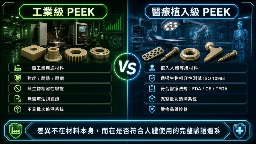
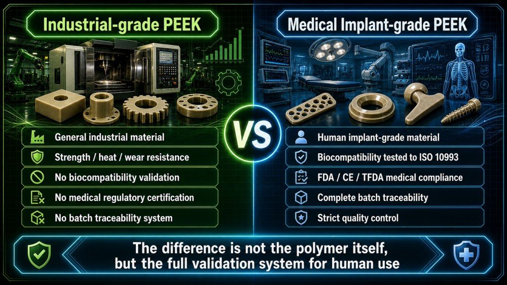
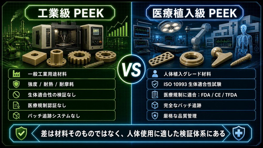
The Most Common Pitfalls for Medical Device Manufacturers:Industrial-grade PEEK and implant-grade PEEK look exactly the same, but their regulatory statuses are worlds apart.
| Dimensions of Comparison | Industrial-Grade PEEK | Implant-Grade PEEK |
| Biocompatibility Certification | 無 | Complete ISO 10993 Series (cytotoxicity, sensitization, systemic toxicity, etc.) |
| Raw Material Purity | General Industrial Specifications | Strictly limit the types and levels of residual monomers and additives |
| Batch Traceability | There are usually no complete records | Certificates of Analysis (CoAs) for all batches, traceable back to the synthesis of the raw materials |
| Applicable Laws and Regulations | No specific regulations | FDA 21 CFR / CE MDR / Taiwan TFDA Medical Device Regulations |
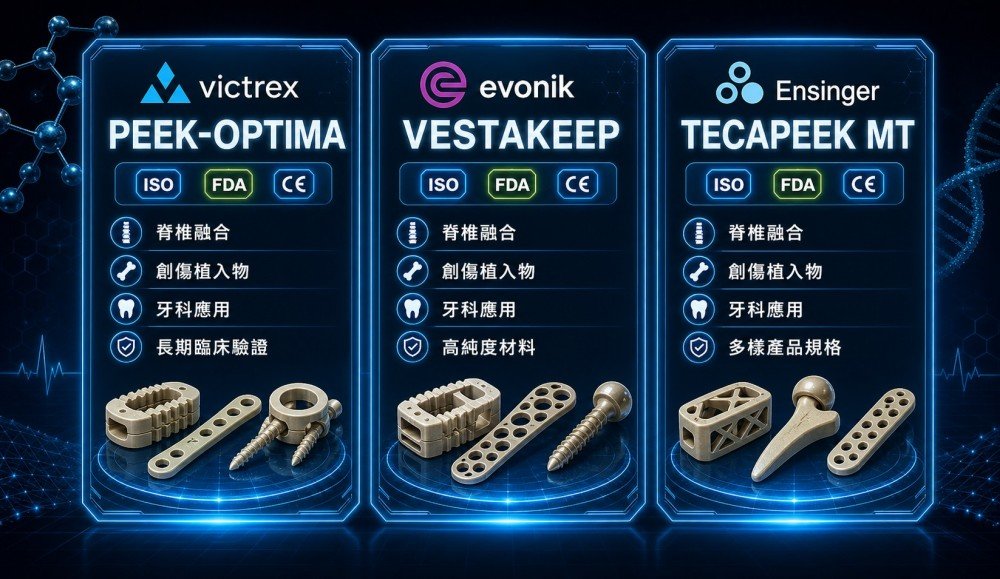
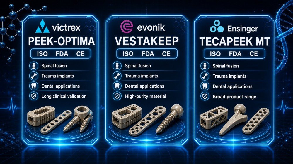
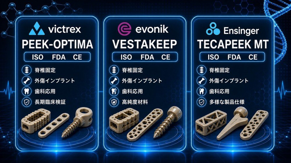
| Represented Brands | Victrex 450G, Ensinger TECAPEEK | Victrex PEEK-OPTIMA™, Evonik VESTAKEEP™, Ensinger TECAPEEK MT |
| Price Differences | Benchmark | 約 2 to 5 times Industrial-grade pricing |
⚠️ Legal Notice: Manufacturing implants using industrial-grade PEEK may result in product recalls, fines, and criminal liability in Taiwan under the Medical Devices Management Act. Before applying for TFDA/CE/FDA certification, please ensure that the raw material batch documentation includes a complete ISO 10993 biocompatibility test report.
Chapter 7: Debunking PEEK Myths—FAQ (10 Questions Total)
Q1: Why is PEEK so expensive? Are there any cheaper alternatives?
The synthesis of PEEK requires condensation polymerization at high temperatures of approximately 300°C. The reaction conditions are harsh, yield control is difficult, and the global market for key raw materials is highly concentrated among a few major suppliers (Victrex, Solvay, Evonik). If your budget is limited, you may consider: ① PEI (Ultem): Temperature-resistant up to 170°C, FDA-compliant, and costs approximately 40% of PEEK; ② PPS: It can withstand temperatures up to 220°C and offers greater chemical resistance, at a cost of approximately 30% that of PEEK. However, neither material can fully replace PEEK’s triple combination of “temperature resistance, chemical resistance, and biocompatibility.”
Q2: Can PEEK be autoclaved?
Yes. With a melting point of 343°C, PEEK is far higher than standard sterilization temperatures (121°C–134°C), making it the material of choice for surgical instruments and sterilization trays. However, please note: ① After repeated steam sterilization (>1,000 cycles), virgin PEEK may degrade slowly due to moisture absorption and thermal cycling stress; ② Ensure that food-grade or medical-grade PEEK (Pure or medically certified grades) is selected, rather than GF/CF-filled grades.
Q3: Can PEEK CF30 be used in medical applications?
CF30 (carbon fiber-reinforced) is itself the subject of controversy regarding biocompatibility—research into the long-term stability of carbon fiber particles within the body is still ongoing, and CF30’s black appearance affects X-ray transmissibility (thereby negating PEEK’s imaging compatibility advantages). Medical applications (especially implants) rely on Pure PEEK 或 HA-Coated PEEK The mainstream choice.
Q4: Can PEEK really replace titanium alloys in orthopedic implants?
To some extent, yes, but not as a direct replacement. The porous surface of titanium alloys allows bone cells to grow directly into it, forming a strong bond; however, the surface of PEEK is biologically inert, so bone cells cannot adhere to it directly. The solution is to use HA (hydroxyapatite) coated PEEK 或 Porous PEEK...making its surface capable of bone conduction. In applications where osseointegration is not required (such as screw fixation for intervertebral fusion devices), PEEK can completely replace titanium alloys and provide better radiographic tracking.
Q5: What is the coefficient of thermal expansion for PEEK? Does it need to be accounted for during design?
The linear coefficient of thermal expansion (CTE) of pure PEEK is approximately 47 × 10⁻⁶ /°C, which is approximately twice that of aluminum alloy. In precision fits, if a workpiece is heated from room temperature (25°C) to operating temperature (200°C), it will expand by approximately 0.82 mm per 100 mm of length—a factor that must be accounted for in the design. The CTE of GF30 can be reduced to approximately 20 × 10⁻⁶ /°C, while that of CF30 can be reduced to approximately 16 × 10⁻⁶ /°C.
Q6: Can PEEK be 3D printed? Are 3D-printed parts as strong as CNC-machined parts?
Yes. The two main methods are FFF (fused filament fabrication) and SLS (selective laser sintering). In 2024, the FDA approved the world’s first 3D-printed PEEK skull implant. However, the interlayer (Z-axis) strength of FFF-printed parts is only about 60–80% of the strength in the XY plane, which is far lower than that of CNC-machined parts. Recommendation: 3D printing is suitable for complex geometries or custom implants, while CNC machining should remain the primary method for load-bearing structural components.
Q7: What is ESD PEEK? How do semiconductor manufacturers choose it?
ESD PEEK controls surface resistance by adding carbon black or carbon nanotubes, keeping it at 10⁴–10⁷ Ω/sq(Electrostatic Dissipation Range), allowing for the safe dissipation of static electricity without generating sparks. Selection Criteria: ① Wafer contact parts → ESD PEEK; ② Chamber structural parts (not in contact with wafers) → Pure PEEK or CF30; ③ Low-contamination parts for cleanrooms → Verify ICP-MS ion elution rate specifications.
Q8: Can PEEK be used in food-contact applications?
Both pure PEEK and specific food-grade formulations are certified under FDA 21 CFR 177.2415 and comply with food contact regulations. However, please note:If glass fiber or carbon fiber particles in the GF30 and CF30 fill levels leach out, they may not comply with food contact regulations.. For food processing equipment, suppliers should be explicitly required to provide “Food Grade” certification documents.
Q9: Which is better suited for CNC machining—PEEK rods or sheets?
Rods are suitable for turning and have good isotropy because they are extruded from the center. Sheets are suitable for milling, but note that their mechanical properties in the thickness direction (Z-axis) are slightly lower than those in the XY plane. General rule: Rods are the preferred choice for rotationally symmetric parts (such as sealing rings and bearings); sheets are preferred for milled parts with complex geometries.
Q10: How can you distinguish between industrial-grade and implant-grade PEEK?
The most reliable method: ① Request a Certificate of Analysis (CoA)——Implant-grade CoA must include the lot number, the manufacturer of the raw materials, and the ISO 10993 test report number; ② Confirm the brand and model—The three leading implant-grade brands are Victrex PEEK-OPTIMA™, Evonik VESTAKEEP™, and Ensinger TECAPEEK MT; ③ Cannot be distinguished by appearance——Since industrial-grade and implant-grade materials have nearly identical color, hardness, and density, verification must be based on documentation.
Chapter 8: A Guide to the Application of PEEK in Semiconductor Equipment
| Application Locations | Recommendation Level | Key Requirements | Important Notes |
| Application Locations | Recommendation Level | Key Requirements | Important Notes |
| Wafer Clamping Fixtures / Carriers | ESD PEEK | Electrostatic dissipation, low contaminant leaching | Verify that the ICP-MS ion extraction efficiency meets the manufacturer's specifications |
| Process Chamber Structural Components | Pure PEEK or CF30 | Resistant to plasma corrosion; dimensionally stable | The carbon fiber precipitation of CF30 in a plasma environment requires an assessment of contamination risks |
| Robotic Arm Parts | PEEK CF30 | High rigidity, lightweight, low thermal expansion | Confirm that it is not intended for electrical insulation purposes |
| Chamber Seals | FFKM or Pure PEEK | Corrosive gases (HF, Cl₂) | For highly corrosive processes, it is recommended to switch to FFKM. |
| Vacuum System Components | Pure PEEK | Ultra-low outgassing rate (< 1.0 × 10⁻⁶ Pa·L/s) | The fugitive gas emission rate data must be confirmed with the supplier. |
Conclusion: Choosing the right PEEK grade is a core competency for precision engineers.
PEEK is not a material where “the most expensive is the best”; rather, it requires a balanced consideration ofLevel (equivalent to functionality) × Scenario (equivalent to disabling conditions) × Compliance (equivalent to legal liability) A systematic approach to material selection across three dimensions. We hope this guide will become the most frequently consulted reference manual for material selection in your office or factory.
We’ve compiled the following resources for engineers: ① A matrix of the five grades × application scenarios, ② A quick reference card for recommended CNC machining parameters, and ③ A chemical compatibility matrix for PEEK × 30 types of media—all available for free download.