

Chengxin Industrial Sealing King | A Practical Guide for Engineers and Purchasing Professionals
Selection Criteria for PTFE, Modified PTFE, Asbestos-Free, Graphite, Spiral-Wound, and Metal-Faced Gaskets
When Selecting a Flange Gasket, First Ask All Five Operating Condition Questions
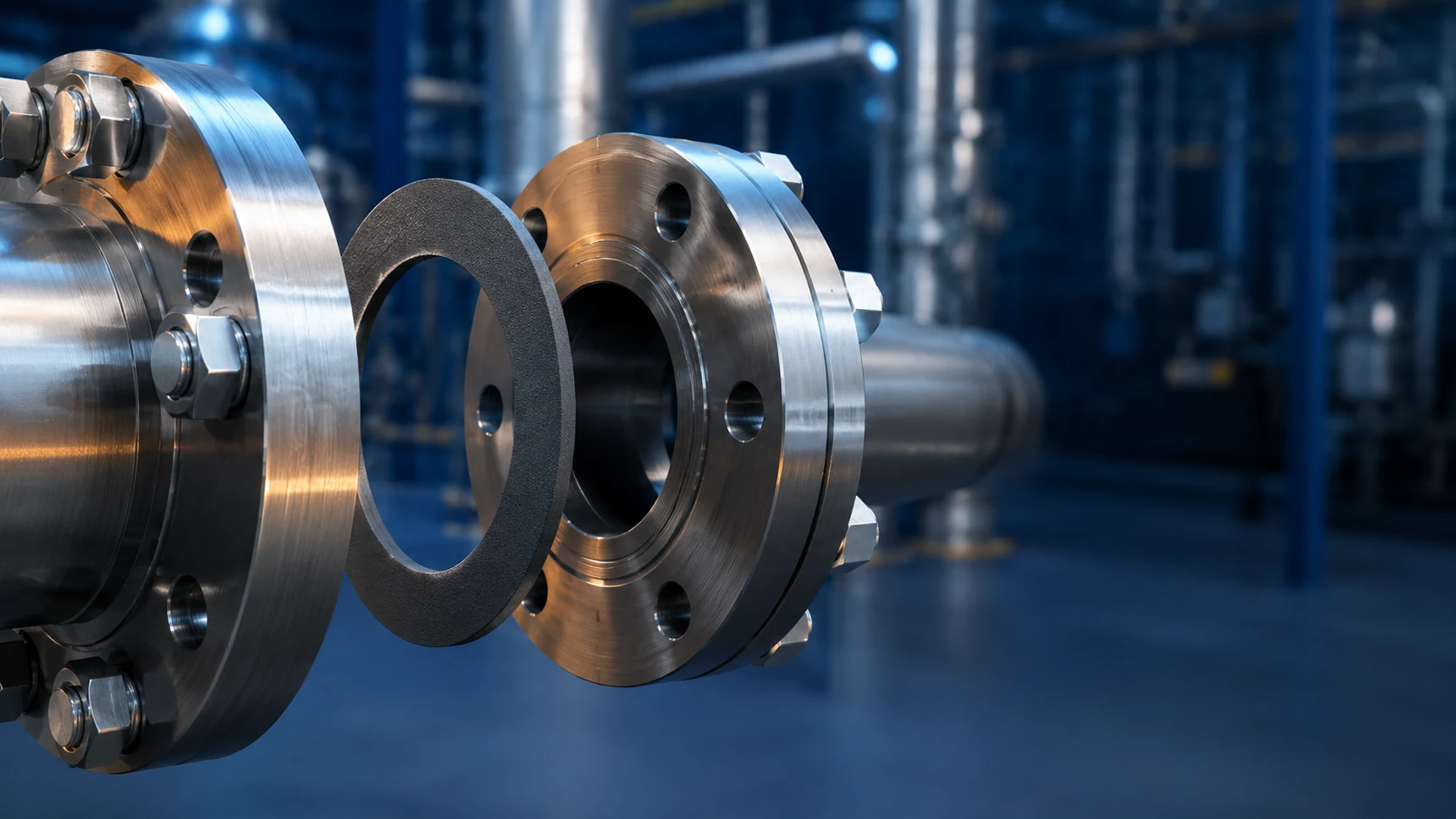
A flange gasket may appear to be nothing more than a thin piece of sealing material, but in reality, it must withstand multiple factors, including media corrosion, temperature fluctuations, internal pressure, bolt clamping force, and uneven flange surfaces. If specifications are determined solely based on “temperature resistance” or “which material is higher-grade,” it is easy to leave actual leak points within the system. Effective flange gasket selection requires evaluating the process medium, temperature, pressure, flange configuration, and delivery requirements all in a single table.
1. Medium: Include the name, concentration, and state of the mixture.
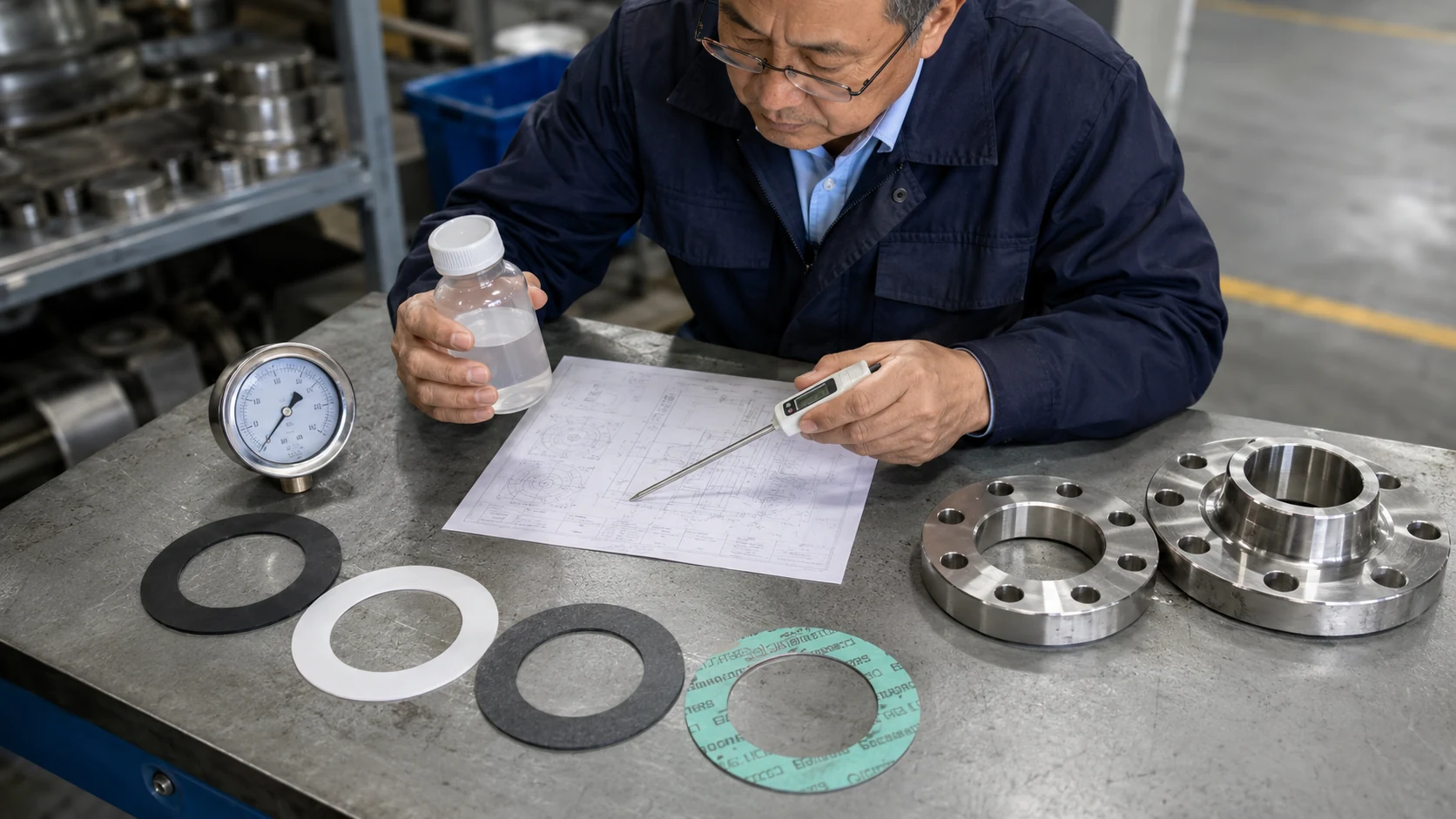
Water, oil, steam, acids, alkalis, solvents, gases, and cleaning solutions each have different effects on materials. Even for substances with the same chemical name, compatibility may vary depending on changes in concentration, water content, or mixture ratios. Selection criteria should include normal service media, cleaning media, media with which the material may come into brief contact, and potential contaminants, and should be reconfirmed using compatibility data for the actual material grade.
2. Temperature: Consider normal values, maximum values, and thermal cycling separately
The normal operating temperature is just the first figure to consider. Start-up heating, shutdown cooling, steam cleaning, heat exchange, and temperature differences between the system and the environment can all cause the gasket to repeatedly compress and rebound. Creep, oxidation, or hardening of the material under prolonged high temperatures may be of greater concern than its ability to withstand instantaneous high temperatures. When requesting a quote, specify the normal, maximum, and minimum temperatures separately, along with the cycling frequency; this will ensure the selected model better matches the on-site conditions.
3. Pressure and Vacuum: In addition to average pressure, there are also fluctuations and pulsations
Internal pressure attempts to push the medium across the sealing interface; vacuum systems, on the other hand, focus on external air infiltration, material outgassing, and long-term dimensional stability. Pump start-up and shutdown, valve switching, and process pulsations may subject flange joints to repeated stress cycles. When selecting a flange, the normal pressure, design pressure, instantaneous peak pressure, vacuum level, and cycle frequency should be specified.
4. Flanges: Standards, Nominal Diameter, Pressure Ratings, and Sealing Surfaces
Although flanges may look similar, their sealing face types, bolt hole patterns, inner and outer diameters, and pressure ratings may still differ. Simply measuring the outer diameter of an old gasket often overlooks the hole positions, sealing face width, and actual contact area. It is recommended to first provide the flange standard, nominal diameter, Class or PN rating, sealing face type, equipment model, and on-site photos, and then follow up with the gasket dimensions.
5. Documentation and Delivery: Supporting Documentation, Traceability, Cleaning, and Packaging
The documentation requirements vary across the food, biotechnology, semiconductor, chemical, and export equipment industries. Certificates of material composition, batch traceability, test specifications, clean packaging, labeling methods, and declarations regarding prohibited and restricted substances should be submitted prior to the quotation so that materials, processes, and documentation can be evaluated together. The scope of documentation provided is subject to the actual materials and supply items.
How Do Flange Gaskets Create a Seal? The Key Is Effective Sealing Stress
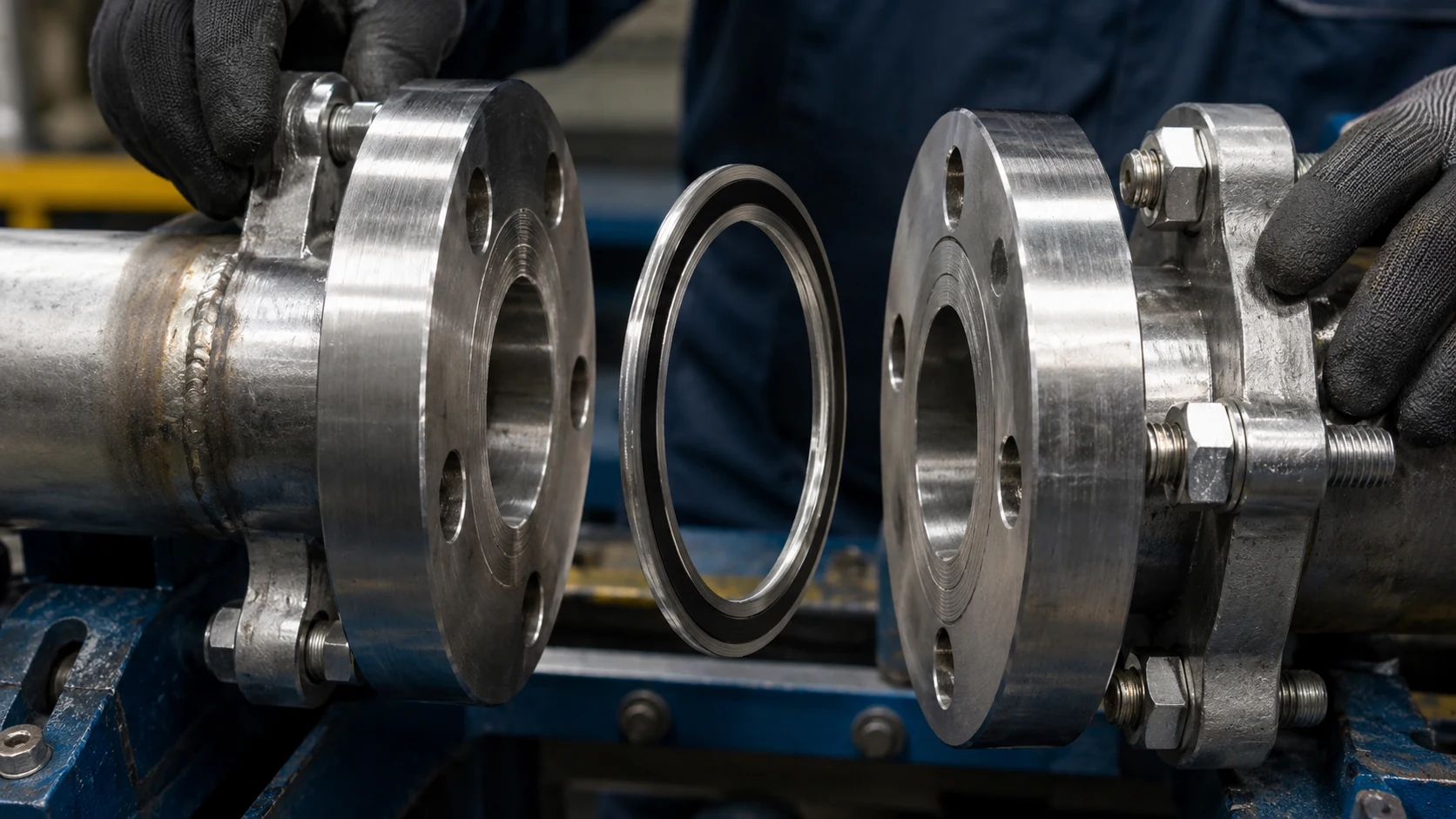
Once the bolts are tightened, the flange transfers the clamping force to the gasket. When properly compressed, the gasket conforms to the minute irregularities on the flange surface, forming a sealing band that prevents the medium from passing through. If the clamping force is insufficient, channels may remain at the interface; if the clamping force is too high, some material may become excessively compressed, extruded, or lose structural stability. The goal of design and installation is to ensure that the effective sealing stress falls within an acceptable range for both the material and the joint system.
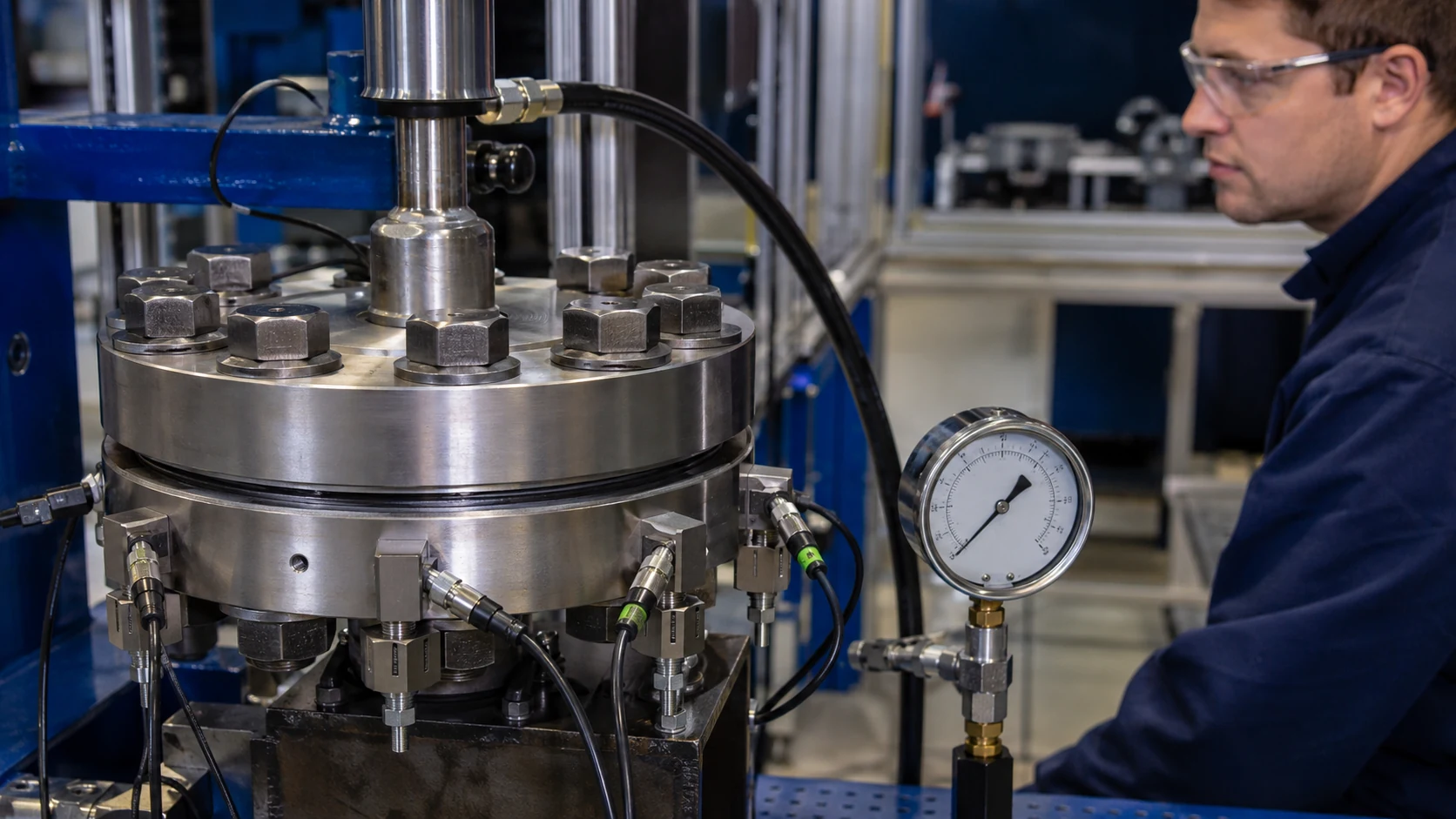
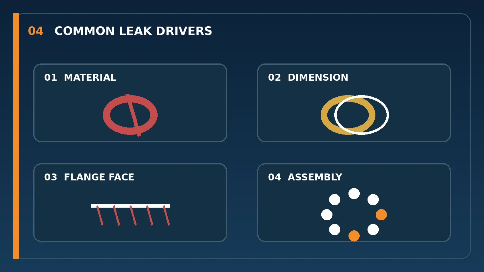
Therefore, when a flange leaks water, air, or other fluids, the cause is not necessarily limited to the quality of the gasket. Incompatibility between the material and the medium, dimensional misalignment, flange warping, surface defects, inconsistent bolt conditions, or an unbalanced tightening sequence can all lead to insufficient local sealing stress. Simply replacing the gasket with a thicker, harder, or more expensive material may not resolve the issue if the root cause is not addressed; the problem is likely to recur.
How to Match O-Rings, Full-Face Gaskets, and Flange Faces
Ring Gasket
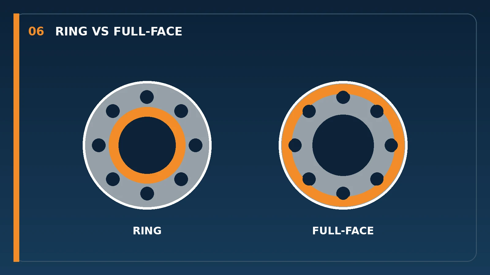
Ring gaskets are typically located within the bolt hole ring and primarily cover the flange sealing surface. Their material utilization and installation method are suitable for many raised-face or specified joint surfaces, but their actual dimensions must comply with flange standards and pressure ratings. The primary scope of ASME PCC-1 includes ring gasket joints located within the bolt hole ring.
Full-Face Gasket
Full-face gaskets extend to the outer edge of the flange and are machined with bolt holes. It is commonly used with flat flanges or in joints requiring full-surface support; however, the number of holes, their diameters, and the hole pattern must be precisely aligned. If bolts are used during installation to forcibly align misaligned holes, the gasket may be sheared, crimped, or subjected to localized high stress.
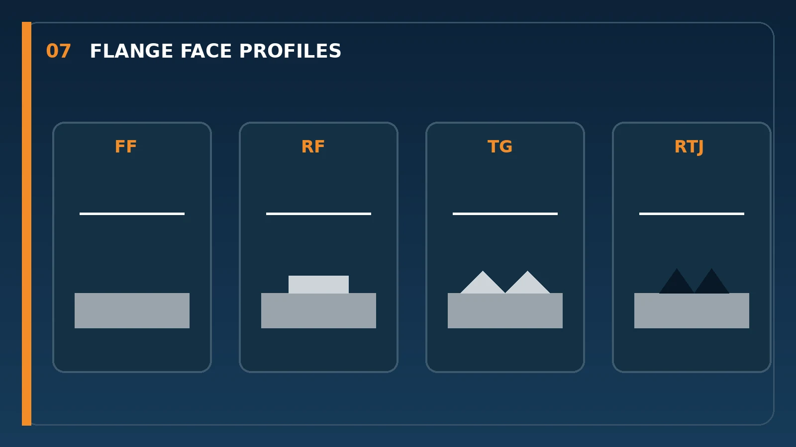
Sealing surfaces such as flat, convex, tongue-and-groove, and annular grooves impose different requirements on the gasket’s shape, contact width, positioning method, and material composition. By first identifying the sealing surface when inspecting a flange, and then verifying the standard and dimensions, you can avoid installing a gasket with a similar outer diameter onto an incompatible mating surface. If on-site markings are unclear, it is recommended to take photos of the front, side, bolt holes, and nameplate.
A Comparison of Six Common Types of Flange Gasket Materials and Structures
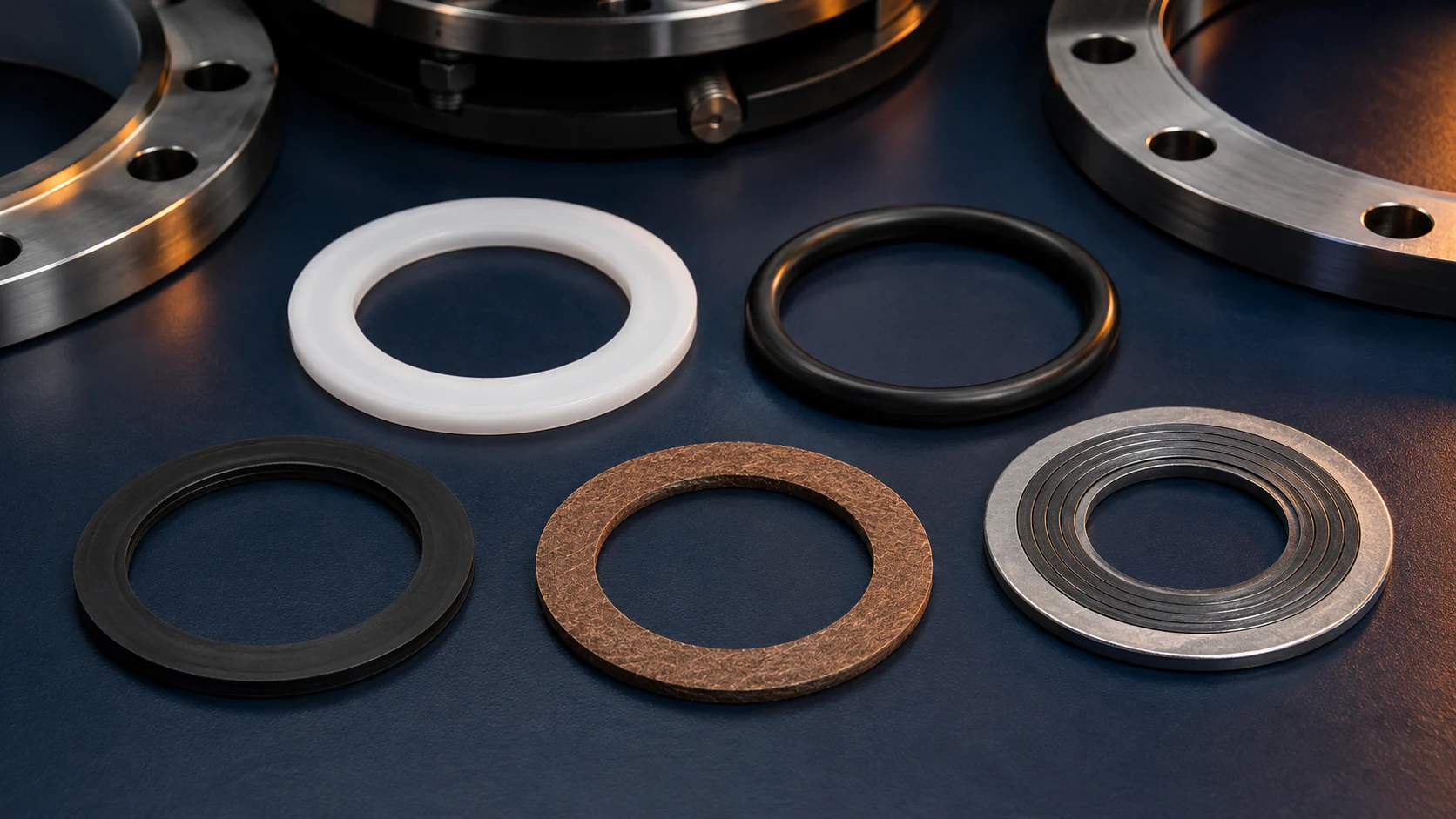
PTFE Flange Gasket
PTFE offers broad chemical resistance and low surface adhesion, making it commonly used in corrosive media, chemical piping, and static joints where cleanliness is critical. When selecting a product, it is still necessary to confirm the temperature, pressure, flange face, and long-term clamping conditions; the creep and cold flow characteristics of pure PTFE must also be factored into the design. Even with the same material designation, resin grades, molding methods, and fillers may still affect performance.
Modified PTFE Gaskets
Modified PTFE is commonly used to improve dimensional stability and long-term pressure resistance through adjustments to the material formulation or microstructure, while retaining the chemical resistance advantages of PTFE-based materials. When selecting this material, verify that the type of filler is suitable for the medium and cleanliness requirements, and check the temperature and pressure ranges against the actual data sheet.
Non-asbestos Compressed Fiber Gasket
Non-asbestos gaskets are typically formed into sheets using a combination of fibers, elastomeric bonding systems, and fillers, and are commonly used in water, oil, air, and general industrial piping systems. Different grades exhibit significant differences in oil resistance, steam resistance, temperature resistance, and compression set; when purchasing, rely on the manufacturer’s grade designations and technical data sheets to avoid simply specifying “non-asbestos.”
Graphite Gasket
Flexible graphite offers heat resistance, conformability, and resistance to thermal cycling, making it commonly used in steam systems, high-temperature equipment, and heat exchange applications. Graphite may also be combined with metal foil, serrated cores, or other support structures. When selecting a product, it is important to consider the oxidation environment, the medium, the compression conditions, and the condition of the flange surfaces.
Spiral Wrap Gasket
Spiral-wound gaskets consist of alternating layers of formed metal strips and filler material, and are commonly used in critical pressure piping, petrochemical, and steam connections. The metal strips, filler material, inner and outer rings, and dimensions must comply with flange standards and service conditions. ASME B16.20 covers the material, dimensional, tolerance, and marking requirements for metal gaskets, including spiral-wound, ring-joint, metal-jacketed, and grooved metal gaskets.
Metal-Clad and Specialty Composite Gaskets
Metal-clad gaskets feature a metal outer layer that protects the inner core and are commonly found in heat exchangers or specialized equipment. Toothed metal cores, corrugated designs, clad structures, or other composite configurations may also be used in applications requiring both strength and sealing performance. These products typically require customization based on equipment drawings, the shape of the mating surfaces, the core material, and fastening conditions.

Temperature, pressure, and time must be considered together
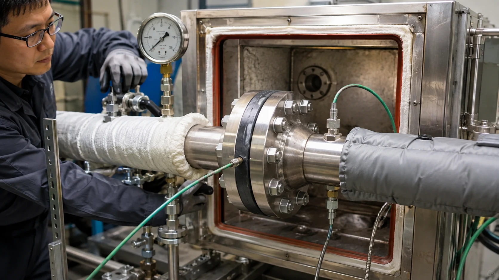
The service limits of a material are not defined by a single temperature or pressure value. Temperature affects the material’s hardness, creep, oxidation, and springback; pressure affects the required sealing stress and the risk of blowout; and time causes these changes to accumulate gradually. If a selection table lists only “80°C, 5 bar,” this information is insufficient to determine whether the conditions apply to startup, shutdown, cleaning, or short-term peak conditions.
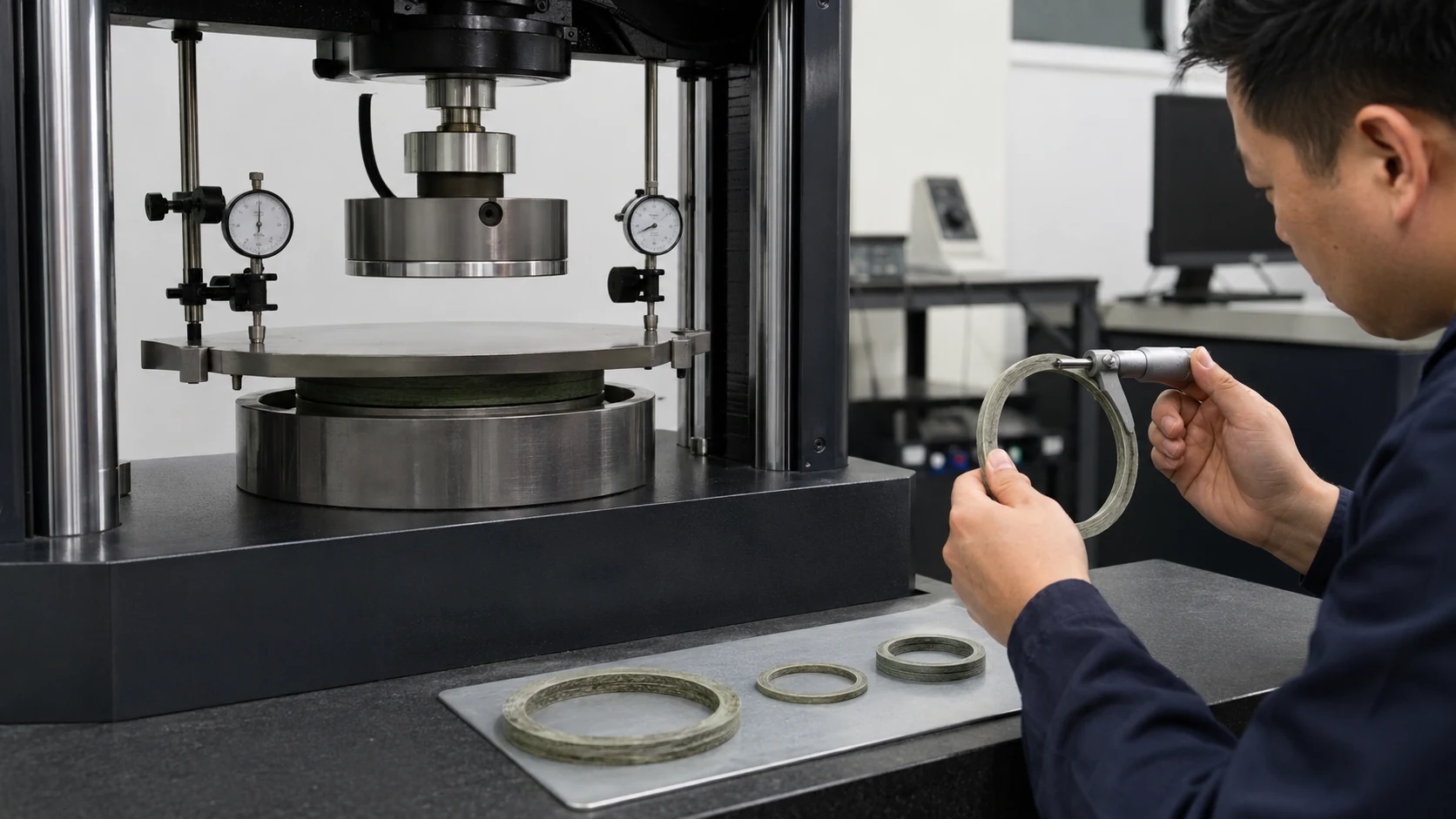
Compressibility helps the gasket conform to the flange surface; resilience helps maintain contact after changes in pressure or temperature. If the gasket is too soft, it may be squeezed out under high pressure; if it is too hard, a higher bolt load may be required to ensure a proper seal. Thickness also affects stress distribution, creep, and lateral stability; therefore, the notion that “thicker is better for leak prevention” is not a reliable rule.
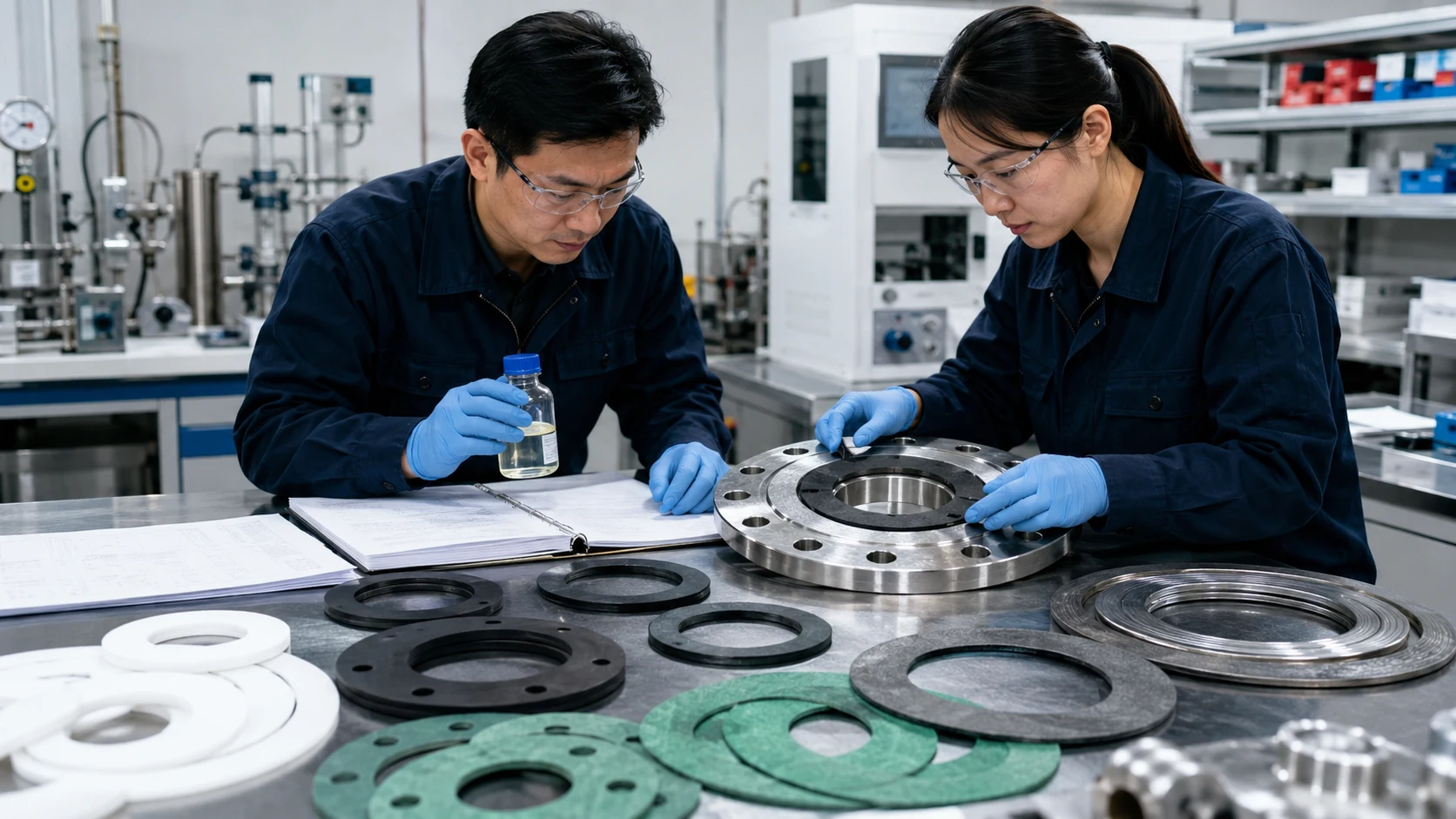
You can also inquire about older models: Convert on-site parts into purchasable specifications
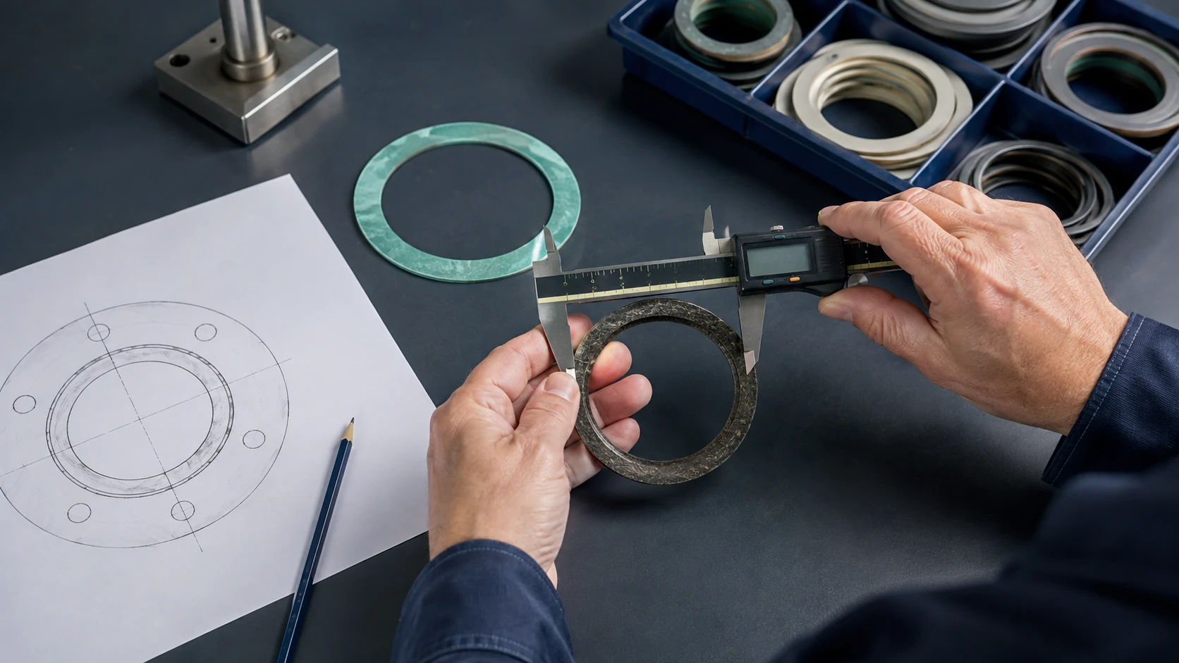
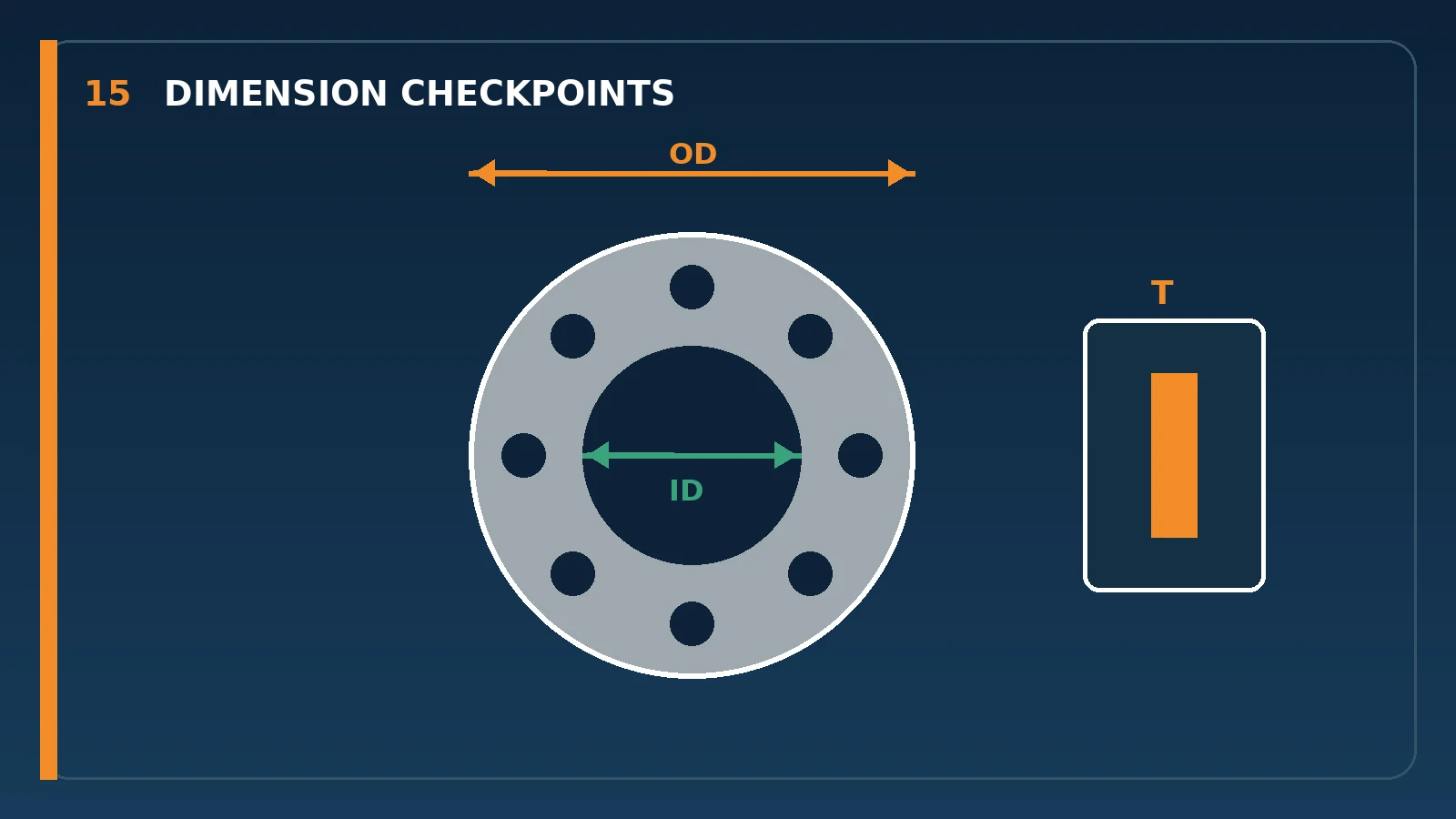
After many years of use, equipment often has only a single old gasket remaining—one that is compressed, swollen, or damaged. In such cases, first take photographs of the overall view, the specific damaged area, the thickness, the flange face, and the equipment nameplate. Then measure the outer diameter, inner diameter, thickness, bore diameter, number of holes, and hole circle. The dimensions of the old gasket may have been distorted and cannot be directly used as tolerances for a new gasket; if necessary, refer back to the flange standard, equipment drawings, or the actual mating surface to reconstruct the dimensions.
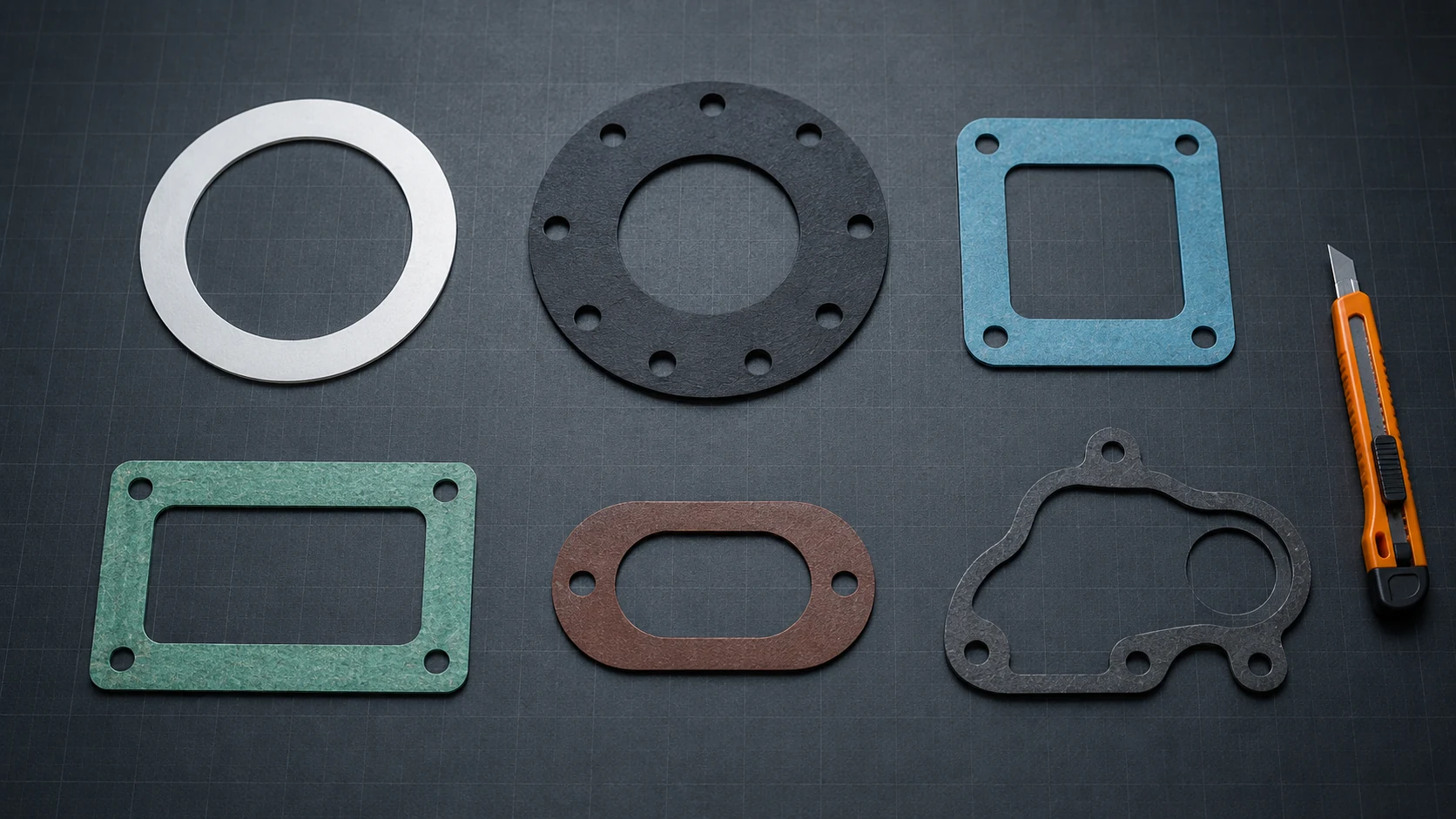
Custom flange gaskets can feature special inner and outer diameters, thicknesses, bolt holes,定位 holes, as well as square, rectangular, oval, and irregular shapes. Manufacturing tolerances, minimum hole diameters, tool compensation, and material utilization vary depending on the material and thickness. Before prototyping, confirm the dimensional references, critical tolerances, burr direction, quantity, and inspection methods.
Common Applications: Industry names are just a starting point; actual operating conditions are the key.
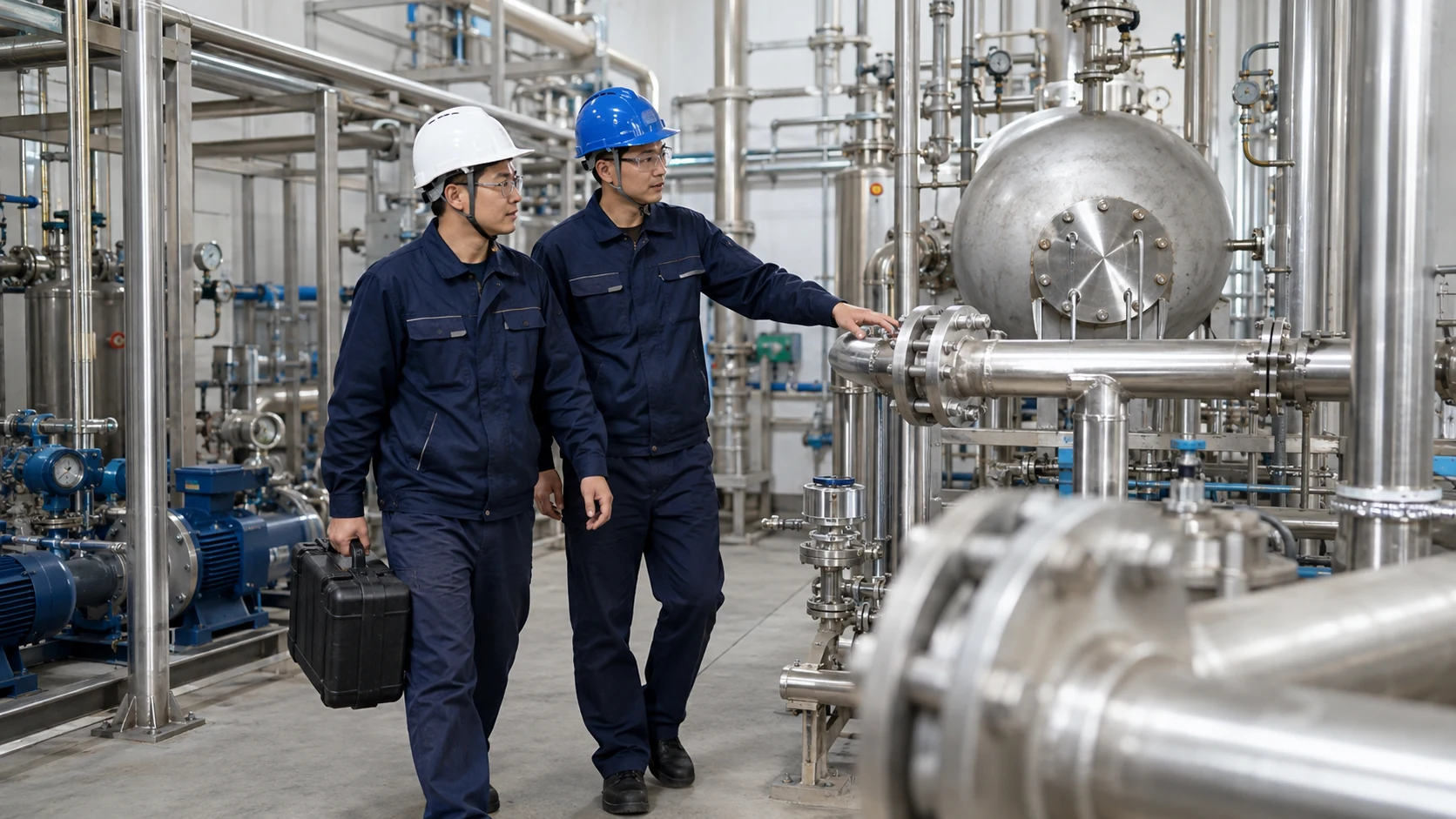
- Chemical and Pharmaceutical Fluid Transfer: Pay close attention to medium concentration, mixtures, temperature, and shutdown cleaning conditions.
- Water Treatment and Utility Systems: Verify water quality, disinfectants, pressure fluctuations, and outdoor aging.
- Semiconductors and Cleanroom Processes: Requirements for low contamination, cleanliness, packaging, and traceability are all addressed simultaneously.
- Food and Biotechnology Equipment: Identify the media with which the equipment comes into contact, the cleaning and disinfection methods, and the required documentation.
- Pumps, Valves, and Tanks: Pay attention to vibration, start-up and shutdown, flange rigidity, and maintenance frequency.
- Vacuum and Gas Systems: Verify outgassing, permeation, cleanliness, and long-term dimensional stability.
Within the same industry, connections involving room-temperature water, corrosive chemicals, steam, vacuum, and high-purity environments may all exist simultaneously; therefore, simply using “semiconductor-grade” or “food-grade” as the sole specification is insufficient. A more effective approach is to treat each leak point as an independent connection and document the medium, temperature, pressure, flange, and maintenance conditions for each one individually.
How to Prepare a Request for Quote: Five Steps to Defining Production Specifications
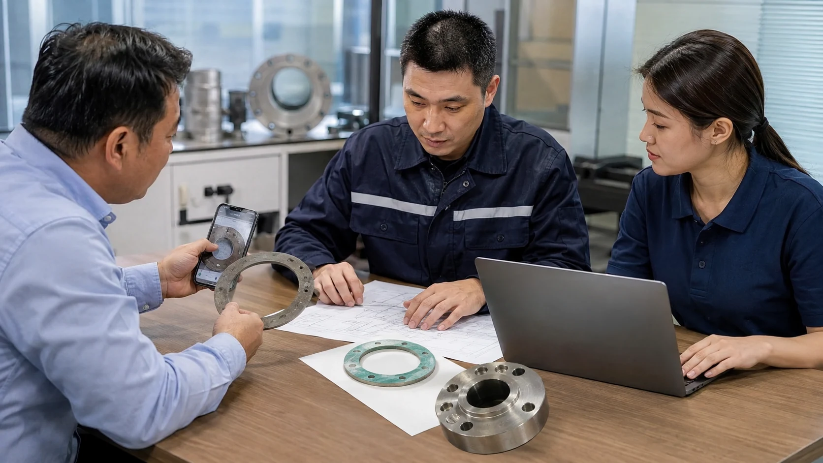
- Please provide the following information about the current situation: equipment model, photos of the flanges, old gaskets, and drawings or hand-drawn dimensions.
- Specify the operating conditions: medium and concentration, normal and maximum temperature, pressure or vacuum, and circulation status.
- Confirm specification details: materials, structure, dimensions, thickness, hole locations, quantity, documentation, and packaging.
- Obtain a Binding Quote: Include the material grade, processing method, inspection requirements, delivery date, and price in a single confirmation document.
- Prototyping and Validation: Arrange for dimensional verification, on-site testing, and the establishment of mass production conditions based on equipment risk.
If the information for a quote request is incomplete, please send us what you have available for now. The key is to clearly distinguish between what is “known” and what is “to be confirmed.” Chengxin can help compile a list of issues based on photos, old samples, flange markings, and operating conditions, thereby preventing procurement and engineering staff from having to repeatedly guess the names of materials.
Flange Gasket Installation: After selecting the right material, you must also ensure that the clamping force is distributed evenly.

Before installation, verify that the equipment has been isolated, depressurized, and cooled down in accordance with on-site safety procedures. After removing any residue from the old gasket, inspect the flange sealing surface for radial scratches, corrosion, warping, or impact damage; Inspect the condition of the bolts, nuts, and washers; center the new gasket, then apply uniform clamping force in stages, diagonally, and progressively, following the approved procedure.
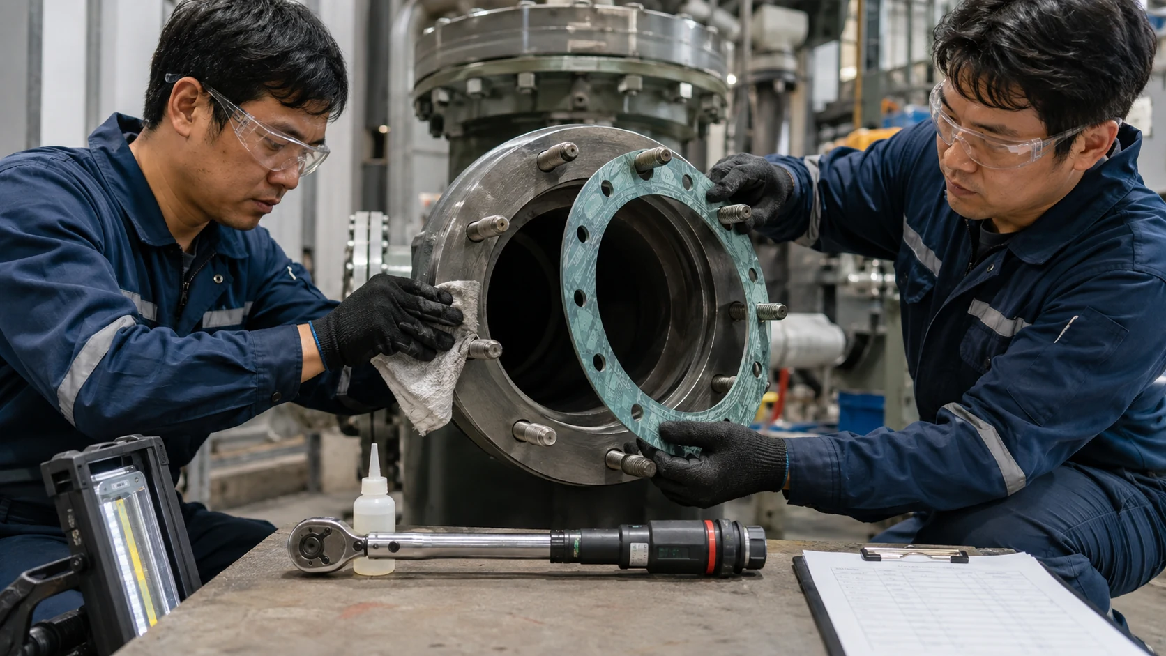
- Use new gaskets; do not reinstall old ones that have been compressed or contaminated.
- Keep the gasket and flange surfaces clean, and check the material specifications and procedures to determine whether adhesives or lubricants are permitted.
- The gasket is centered; its inner diameter does not intrude into the flow path, and its outer diameter does not interfere with the bolts at the hole locations.
- Tighten gradually in multiple stages, adjusting the tool, bolt friction, and target load.
- Heating, pressurization, and commissioning were carried out in accordance with the equipment procedures, while monitoring the joints and recording operational data.
ASME PCC-1 provides assembly guidelines for bolted flange joints in pressure vessels and may serve as a reference for companies in establishing procedures, training, and quality control. The actual tightening torque, lubrication methods, retightening conditions, and acceptance criteria must be determined based on the equipment design, material data, and approved engineering procedures.
Failure Diagnosis: Examine the Shape of the Damage to Identify the Root Cause
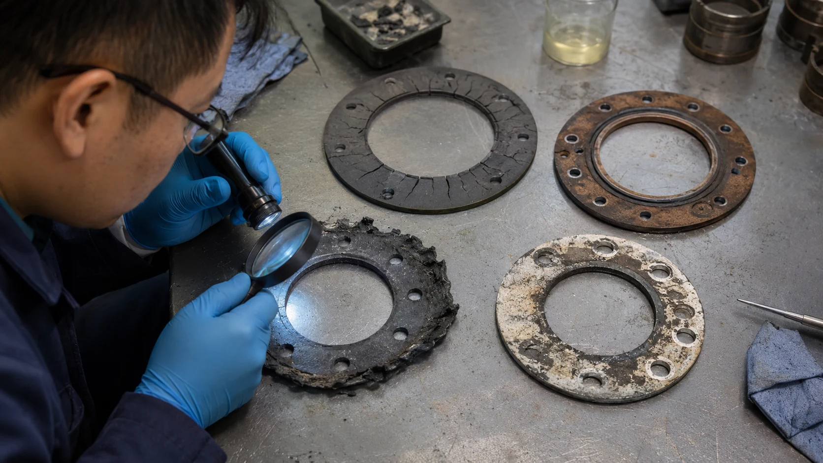
Swelling, hardening, softening, or cracking
First, check the compatibility of the materials with the process medium, concentration, temperature, and cleaning solution. Even if the damage is localized, verify whether the process medium is creating stagnant areas on the flange face or whether the equipment has come into contact with chemicals not listed in the specifications.
Eccentric Indentation and Unilateral Leakage
This may be due to a misaligned gasket, an incorrect size, misalignment of the flanges, or uneven bolt load. Check whether the indentations are continuous around the circumference, and compare the condition of each bolt with the contact marks on the sealing surface.
Edge extrusion, tearing, or blowing out
Possible causes may include internal pressure, excessively thick gaskets, material strength, flange clearance, localized loads, or structural design choices. For failures of this type, equipment safety and procedures must be addressed first, followed by verification of the joint design by the engineering team.
Leakage began only after thermal cycling
This may be related to material creep, insufficient springback, thermal deformation of the flange, bolt load relaxation, or surface conditions. Keeping records of temperature rise and fall curves, pressure readings, operating hours, and maintenance history can help identify the root cause more quickly than simply examining a damaged gasket.
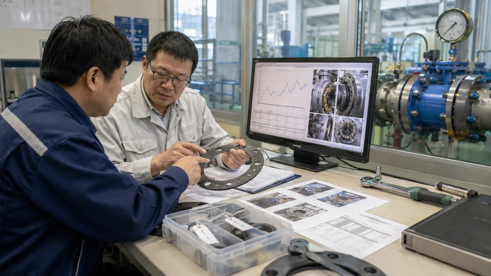
Reliable flange sealing is not a one-time purchase, but rather a cycle of specification, stocking, installation, operation, inspection, and improvement. Keeping records of material grades, dimensional drawings, lot numbers, installation dates, tightening procedures, service media, temperature and pressure conditions, and the condition of the flange upon disassembly allows the next procurement process to directly reference verifiable specifications and helps determine whether problems stem from the material, design, assembly, or equipment condition.
Flange Gasket FAQ
I don't have any drawings, just some old gaskets. Can I get a quote?
Sure. Please first provide photos of the old part showing both sides, its thickness, inner and outer diameters, hole locations, flange face, and the equipment nameplate. Then, please provide the medium, temperature, and pressure. The old part may have warped, so the official specifications will still need to be verified against the flange or equipment documentation.
Are PTFE flange gaskets definitely better than rubber or non-asbestos gaskets?
There is no single ranking for these materials. PTFE is valued for its chemical resistance and cleanliness; rubber offers elasticity; and non-asbestos sheet materials are suitable for a wide range of general operating conditions. The specific grade should be selected based on the medium, temperature, pressure, flange surface, load, and cost.
Does a thicker gasket provide a better seal?
Thickness affects compression, creep, springback, and lateral stability. When the flange is flat, increasing its thickness arbitrarily may increase the risk of extrusion and load loss. The thickness should be determined based on the material data and joint design.
Can flange gaskets be reused?
In general, gaskets should be replaced with new ones after disassembly and reassembly, as the old ones have been compressed, contaminated, and subjected to thermochemical reactions. Whether a particular design is reusable must still be determined in accordance with the manufacturer’s specifications and approval procedures.
Are flange gaskets and O-rings interchangeable?
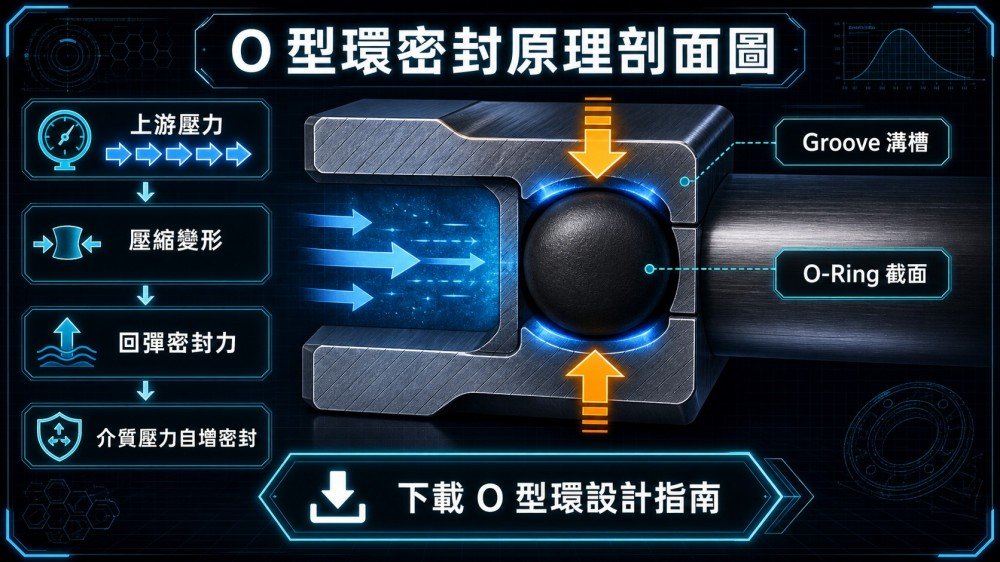
The cross-sections, grooves, and load-bearing designs of the two differ. O-rings typically require a matching groove, while flat gaskets are compressed against the flange sealing surface. They should be selected based on the original joint design to avoid direct substitution.
Is it necessary to know the material grade when requesting a quote?
You can start by describing the operating conditions. Provide details on the medium, concentration, temperature and pressure, flanges, dimensions, quantity, and any existing issues so that the supplier can narrow down the options for materials and design.
Can you produce parts with special shapes and hole patterns?
We can evaluate ring-shaped, fully flat, square, rectangular, oval, and irregularly shaped parts based on drawings, samples, and material thickness. To provide a formal quote, we need to confirm the dimensional reference, tolerances, hole locations, quantity, and inspection methods.
What is the difference between ASME B16.20 and B16.21?
B16.20 primarily covers various types of metal gaskets; B16.21 covers the types, dimensions, materials, dimensional tolerances, and marking of nonmetallic flat gaskets. The actual selection must still be based on flange standards, equipment design, and operating conditions.
Provide Chengxin with the operating conditions, old samples, or drawings, and first clarify the specifications.
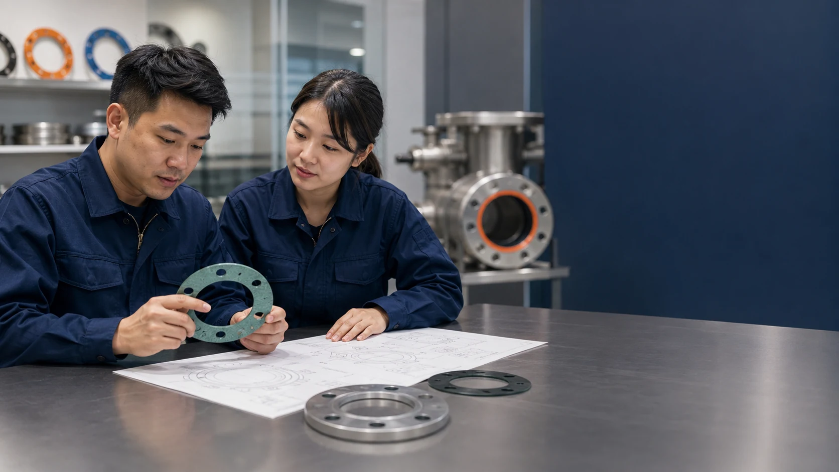
Whether you’re dealing with recurring flange leaks, non-conforming standard part dimensions, discontinued material grades, or only have old samples on-site, you can start by submitting your existing data to Chengxin Sealing King. Our team will begin by organizing the details regarding the medium, temperature, pressure, flange face, dimensions, quantity, and documentation requirements to help narrow down the options to PTFE, modified PTFE, non-asbestos, graphite, spiral-wound, or special composite structures, and then confirm the quotation, prototyping, and delivery terms.
Chengxin International Trading Co., Ltd. | +886 905481781 | 0905-481-781 | service@chengsyin.com
Sources of Technical Audits
- ASME B16.20 – Metallic Gaskets for Pipe Flanges
- ASME B16.21 – Nonmetallic Flat Gaskets for Pipe Flanges
- ASME PCC-1 – Bolted Flange Joint Assembly for Pressure Boundaries
- Chengxin Sealing King | Industrial-Grade Flange Gasket Product Page
- Chengxin Sealing King | Contact Information
The edition, scope of application, and official terms shall be governed by the official version and approved engineering documents obtained at the time of design, procurement, or construction. This document is intended for preliminary data compilation and communication regarding requests for quotations; official specifications must still be confirmed based on the actual equipment and operating conditions.