

O-rings are the most widely used sealing components in the world; they are found everywhere, from household faucets to deep-sea oil drilling equipment, and from craft beer brewing systems to semiconductor manufacturing equipment. However, despite their small size, choosing the wrong material or installing them incorrectly can bring an entire plant to a standstill or even lead to workplace safety incidents. This guide will consolidate all the essential information in one placeMaterial Lightning Protection, Compression Ratio Calculations, Installation SOP, and 8 Major Failure Diagnoses, helping engineers and procurement professionals thoroughly resolve all questions regarding O-ring selection.
Chapter 1: What Is an O-Ring? Understand the Principles of Sealing in 60 Seconds
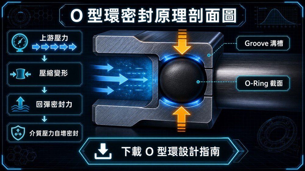
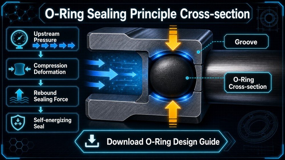
Sealing Principle: Seals Everything Using “Compression-Rebound Force”
An O-ring has a perfectly circular cross-section. When it is installed into a precision-machined “groove,” the mating flange face or bore will compress and deform its cross-section, causing the rubber material of the O-ring to expand outward and tightly seal every surface gap in the groove. When a fluid or gas attempts to escape from the contact surface, the O-ring’s resilience actively counteracts the fluid pressure; the higher the pressure, the greater the resilience, and the better the sealing performance—this is the O-ring’s most fascinating “self-pressurizing seal” characteristic.

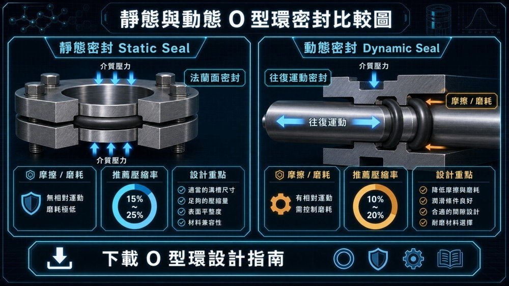
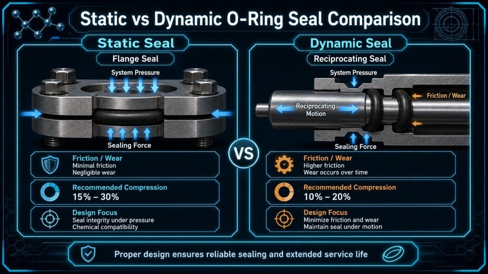
Static Seals vs. Dynamic Seals: There’s a Big Difference Between the Two
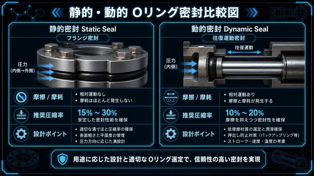
The most important classification of O-ring applications is “static” versus “dynamic,” which directly influences the selection of material hardness and compression ratio:
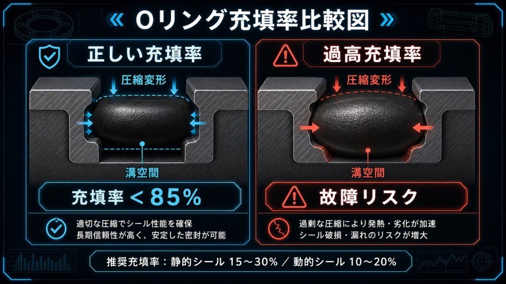
- Static Sealing: There is absolutely no relative movement between the sealing surfaces, such as flange mating surfaces or end cap bolt seals. The compression ratio can be set relatively high (15%–30%) to ensure a complete seal.
- Dynamic Sealing: There is continuous reciprocating or rotational motion between the sealing surfaces, such as in the piston rod of a hydraulic cylinder. The compression ratio should be set relatively low (10%–20%) to reduce friction, wear, and heat generation.
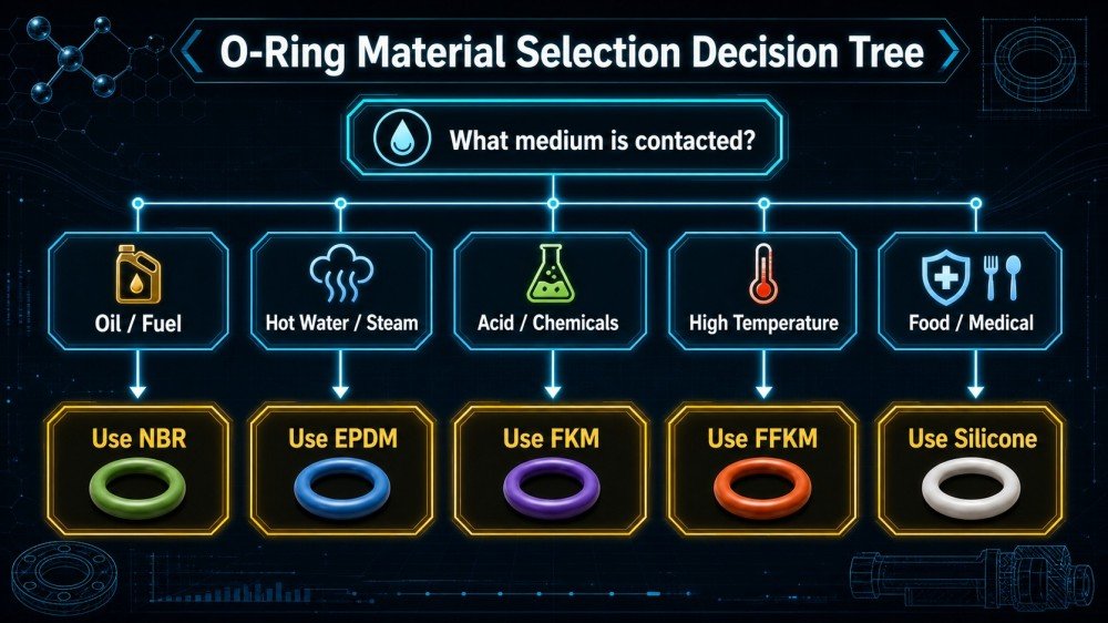
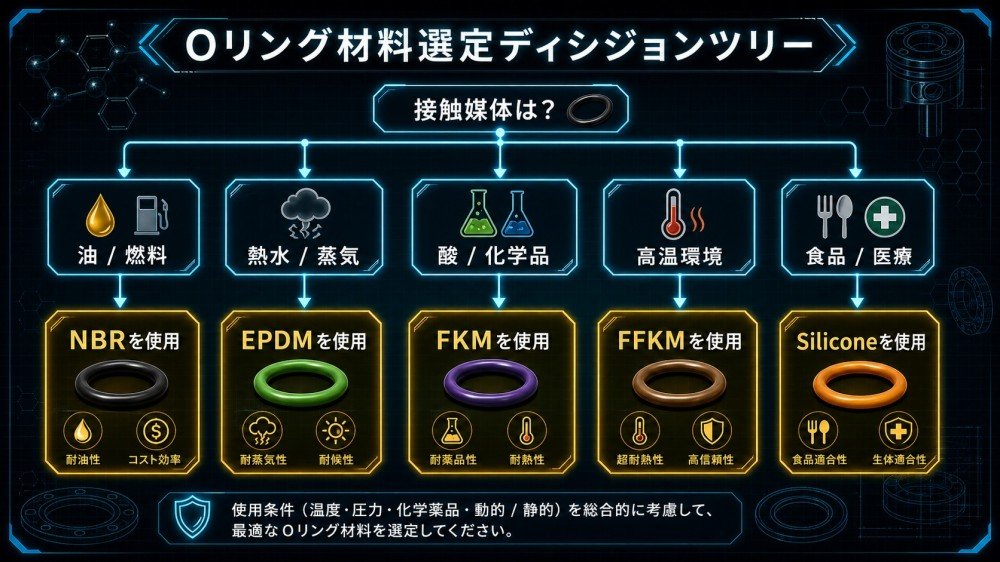
Chapter 2: A Guide to Avoiding Pitfalls with Four Major Materials—Choosing the Wrong One Is More Dangerous Than Not Installing It at All
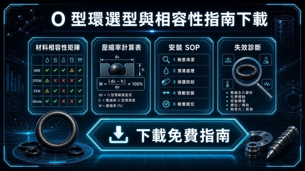
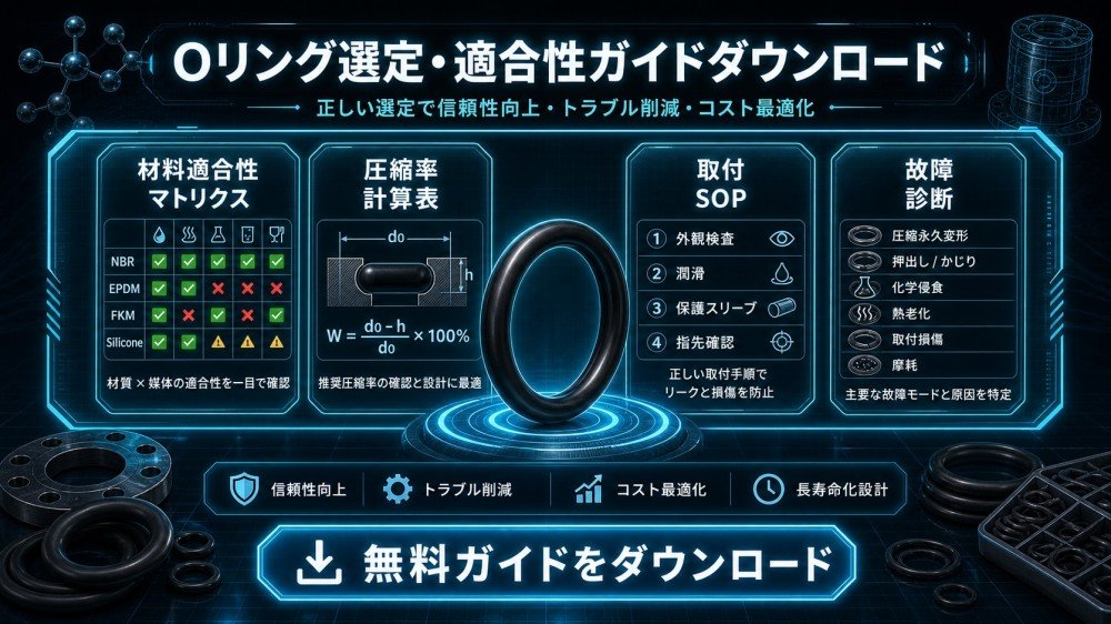
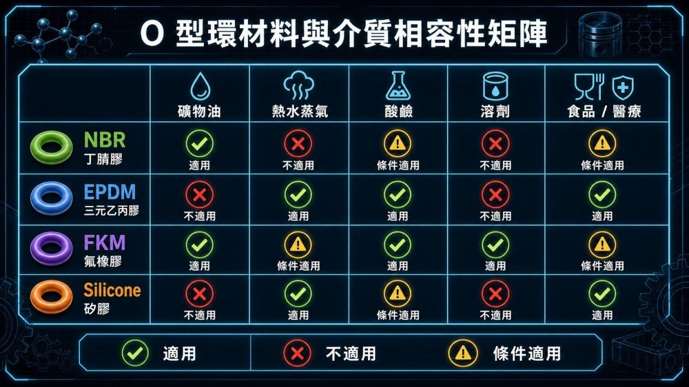
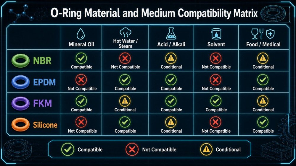
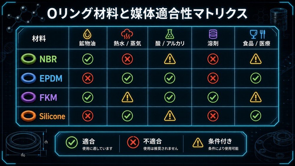
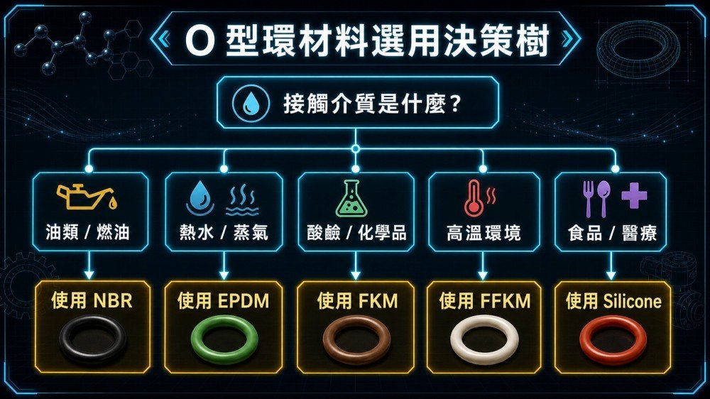
Choosing the wrong material is the most common—and most costly—cause of O-ring failure. Below are the four most widely used materials on the market today, along with explanations of the most critical “situations where their use is prohibited”:
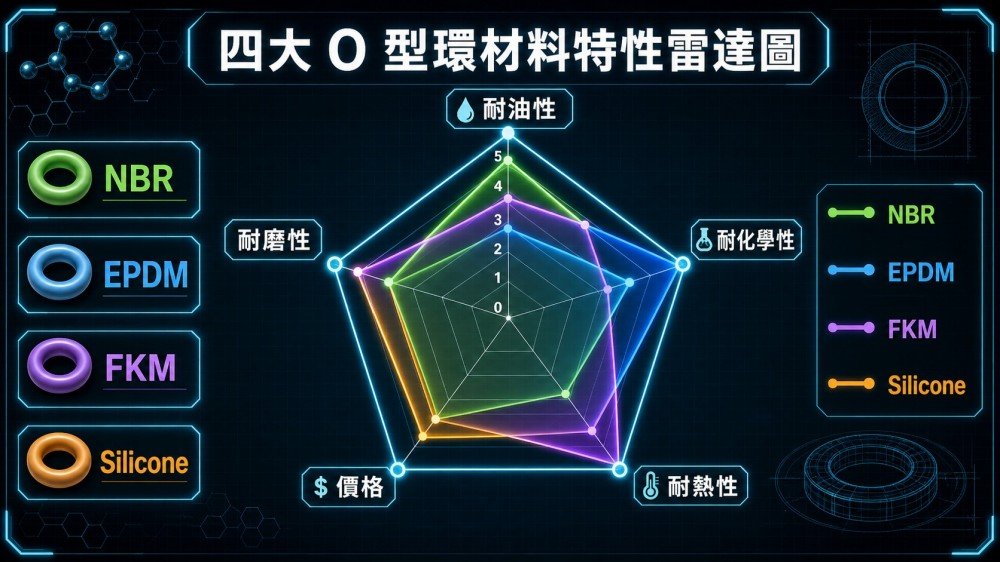
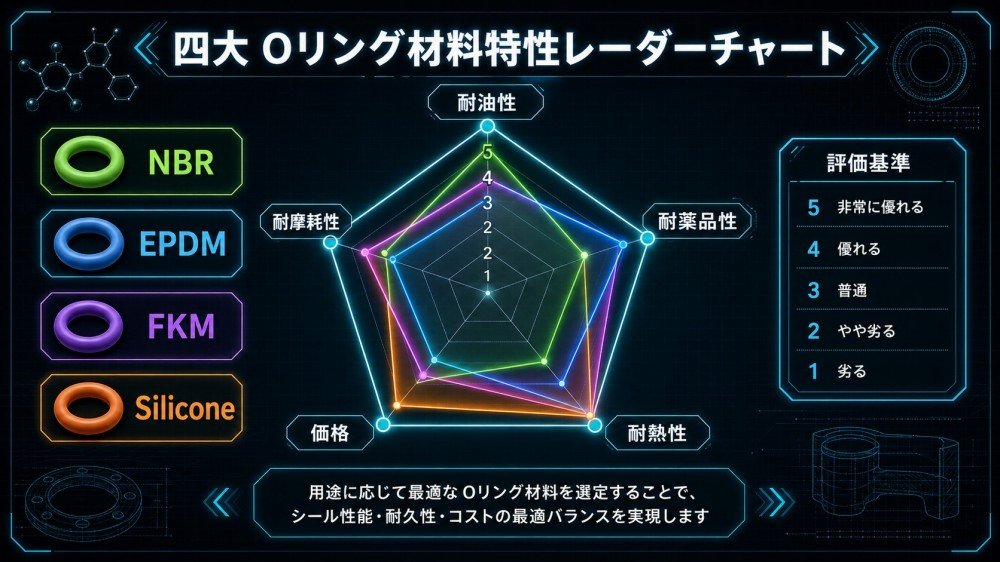
Comprehensive Comparison Chart of the Four Major Materials
| Material | Temperature Range | Oil resistance | Chemical resistance | Core Strengths | ⛔ Deadly Zone | Ideal Scenarios |
| NBR (Nitrile Rubber) | -30°C to 100°C | ★★★★★ | ★★ | Resistant to mineral oil and hydraulic oil; the most affordable and versatile industrial sealing material | ❌ Not resistant to ozone, outdoor weathering, or polar solvents (such as ketones and esters) | Hydraulic Cylinders, Fuel Systems, Air Compressors, General Machinery |
| EPDM (Ethylene Propylene Diene Monomer) | -40°C to 130°C | ★ (Extremely Poor) | ★★★★★ | Resistant to ozone, weathering, hot water, and steam; suitable for use with drinking water | ❌ Do not come into contact with any oil products under any circumstances! It swells rapidly and fails upon contact with mineral oil. | Water supply systems, water heaters, outdoor piping, automotive cooling systems |
| FKM (Fluorocarbon Rubber / Viton) | -20°C ~ 200°C | ★★★★★ | ★★★★ | Resistant to high temperatures, most oils, and chemicals; the most widely used high-performance material | ❌ Elasticity drops sharply at extremely low temperatures (below -20°C), making it unsuitable for extreme cold in polar regions | Petrochemical plants, automotive engines, aerospace equipment, high-temperature piping |
| Silicone | -50°C ~ 200°C | ★ (Extremely Poor) | ★★ | Extremely wide temperature range, non-toxic, certified for food and medical use, soft with excellent elasticity | ❌ Do not come into contact with mineral oil, gasoline, or lubricating oil! It will rapidly swell and fail upon contact with oil. | Food processing machinery, medical equipment, environments with alternating high and low temperatures, electronic equipment |

High-End, Advanced Materials: FFKM and HNBR
- FFKM (Perfluoroelastomer): With chemical resistance comparable to that of “the PTFE of the rubber world,” it withstands virtually all chemicals and is widely used in semiconductor manufacturing processes (such as etching chambers) and high-end aerospace equipment.The price is 10 to 100 times that of FKM, Please do not use this option unless necessary.
- HNBR (Hydrogenated Nitrile Rubber): Based on NBR, this material offers enhanced heat resistance (up to 150°C) and ozone resistance, making it the material of choice for automotive air conditioning systems and oil well drilling.
Chapter 3: Compression Ratio Calculations and Groove Design—Key Figures Every Engineer Should Know
This is the technical core that is completely missing from the top 10 SERP results, and it is the design foundation that B2B engineers need most.
Compression Ratio Formula and Recommended Range
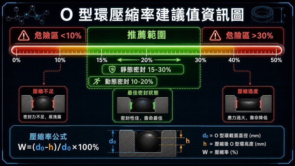
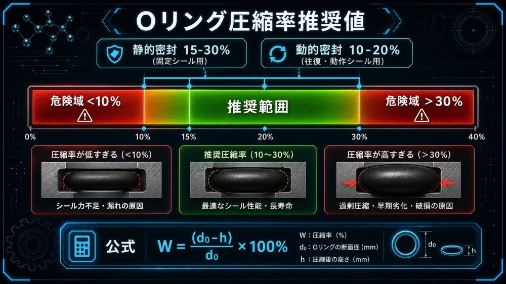
The compression rate is the most critical design parameter determining the sealing performance and service life of an O-ring. The calculation formula is as follows:
W = (d₀ − h) / d₀ × 100 / (1 + TP³ / T)
Among these:
- d₀ = O-ring cross-sectional diameter (wire diameter in the free state, mm)
- h = Groove Depth (mm)
Recommended compression ratio range:
- Static Seals (Axial / Radial):15%–30%
- Dynamic Reciprocating Seals:10%–20%
- Dynamic Rotating Seal:5%–15%(Must be used with sufficient lubrication)
⚠️ A higher compression ratio isn't necessarily better! When the compression ratio exceeds 30%, stress concentration in the O-ring significantly shortens its service life, and “compression set” is more likely to occur in high-temperature environments, leading to long-term seal failure.
Filling Rate: Another Key Parameter That Is Often Overlooked
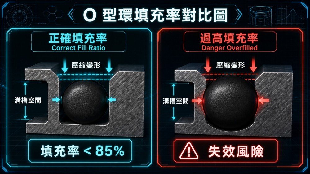
In groove design, in addition to the compression ratio,The fill rate must be less than 85%. This is to ensure that there is sufficient space within the groove to accommodate:
- Dimensional Tolerances of O-Rings Themselves
- Absorption and swelling that may occur in O-rings after contact with fluids
- Thermal Expansion as Temperature Rises
If the fill ratio exceeds 85%, the O-ring will have no room to expand, resulting in enormous additional stress within the groove and accelerating failure due to compression set.

Chapter 4: Proper SOP Installation—Avoiding Cuts, Distortions, and Helical Failure
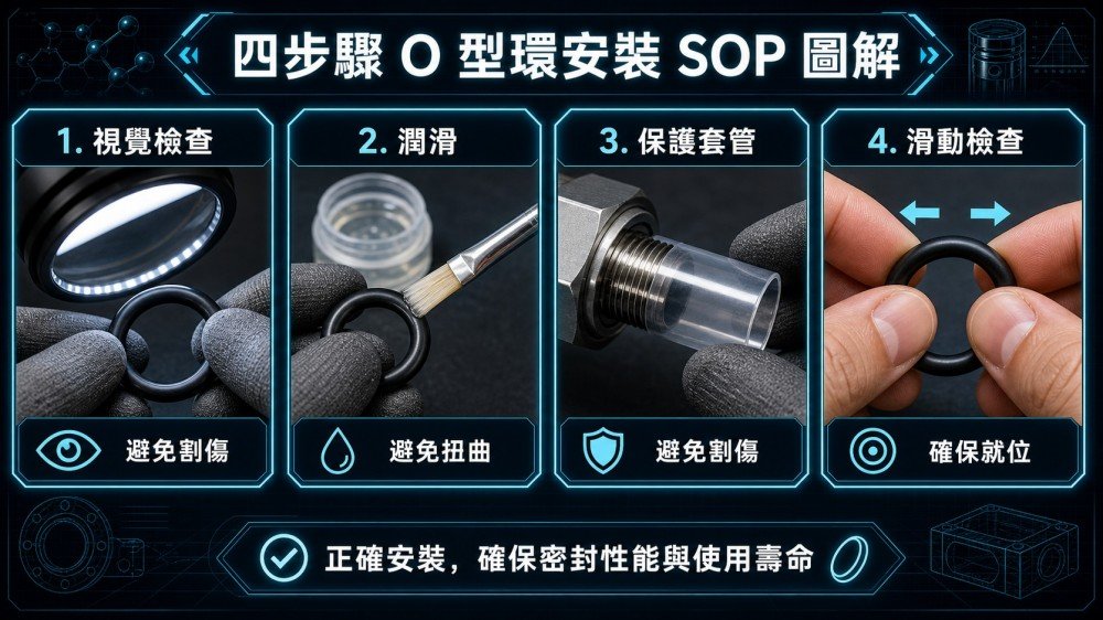
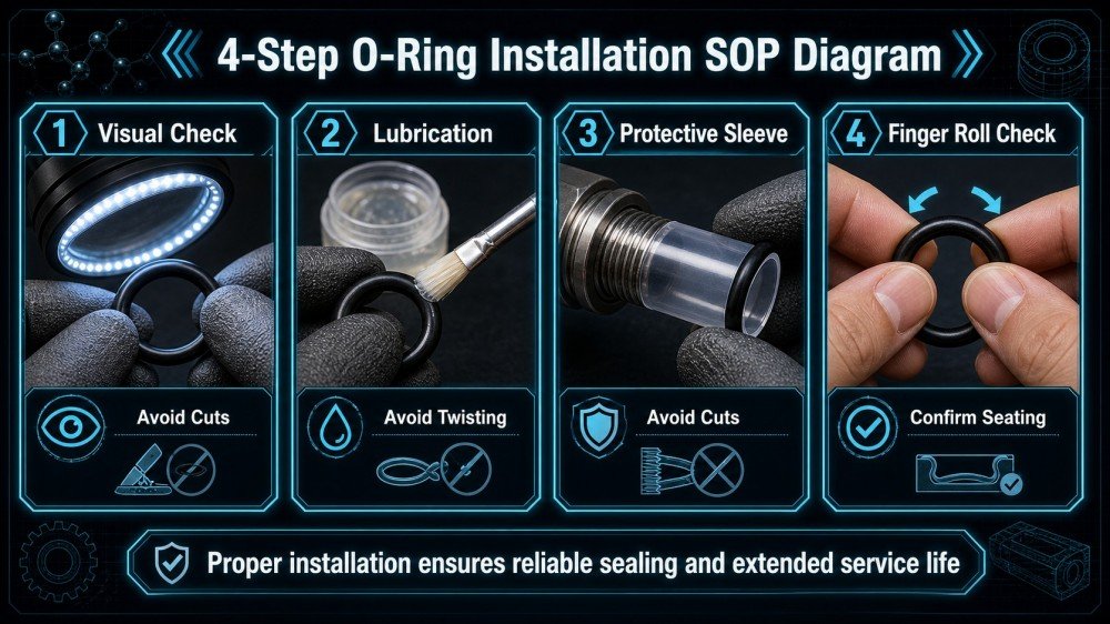
According to statistics from industrial safety authorities and seal manufacturers, improper installation is the leading human-caused factor in O-ring failure. Please use the following four steps as the standard operating procedure (SOP) for plant maintenance:
Four-Step Installation SOP
Step 1: Visual Inspection Before Installation
After removing the new O-ring, carefully inspect it under sufficient lighting for manufacturing defects (burrs, air bubbles, scratches). Stretch it to check for cracks. If any defects are found, replace it immediately; do not use it.
Step 2: Apply a compatible lubricant
Before installation, apply a thin layer of lubricant compatible with the medium (such as silicone grease or petroleum jelly). The lubricant serves three key functions: reducing friction during installation to prevent cuts; helping the O-ring slide smoothly into the groove to prevent distortion; and filling microscopic depressions on the O-ring’s surface to enhance the initial seal.
⚠️ Note: Silicone grease must not be used on silicone O-rings, as material incompatibility can cause the silicone to swell.
Step 3: Sleeving Method (to Prevent Cuts from Threads)
When installing an O-ring over an external threaded section, you must first slip on a thin-walled protective sleeve with a diameter slightly larger than the thread (or wrap the thread with tape) so that the O-ring can slide over the thread while protected by the sleeve; then remove the protective sleeve. Forcing the O-ring directly over the threads is the primary cause of O-ring cuts.
Step 4: Verify that the cross-section is not twisted (to prevent spiral failure)
Once the O-ring is fully in place, gently roll your finger around the groove once and visually inspect the O-ring to ensure that the color and luster are uniform and consistent around the entire circumference. If there are obvious shiny twist marks in any section, this indicates that the cross-section has become distorted, and the O-ring must be removed and reinstalled.Installing an O-ring with a distorted cross-section is the starting point for future helical torsional failure.

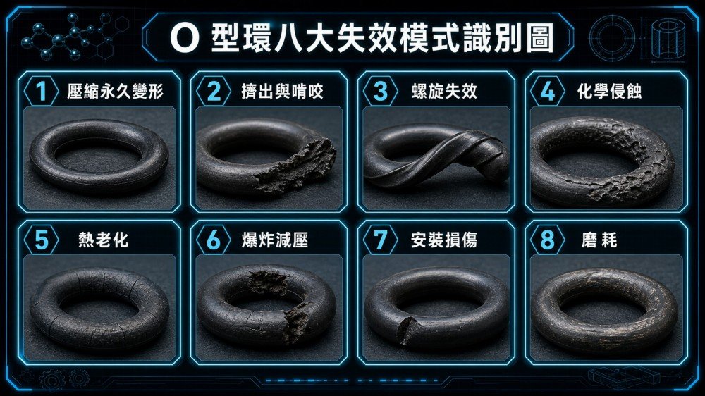
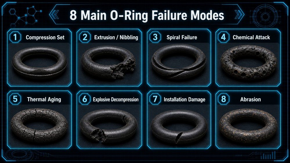
Chapter 5: A Guide to Diagnosing the 8 Major Causes of Failure—Why Does Your O-Ring Keep Leaking?

Failure Diagnosis Quick Reference Chart
| Failure Mode | Visible Features | The Most Common Causes | Corresponding Solution |
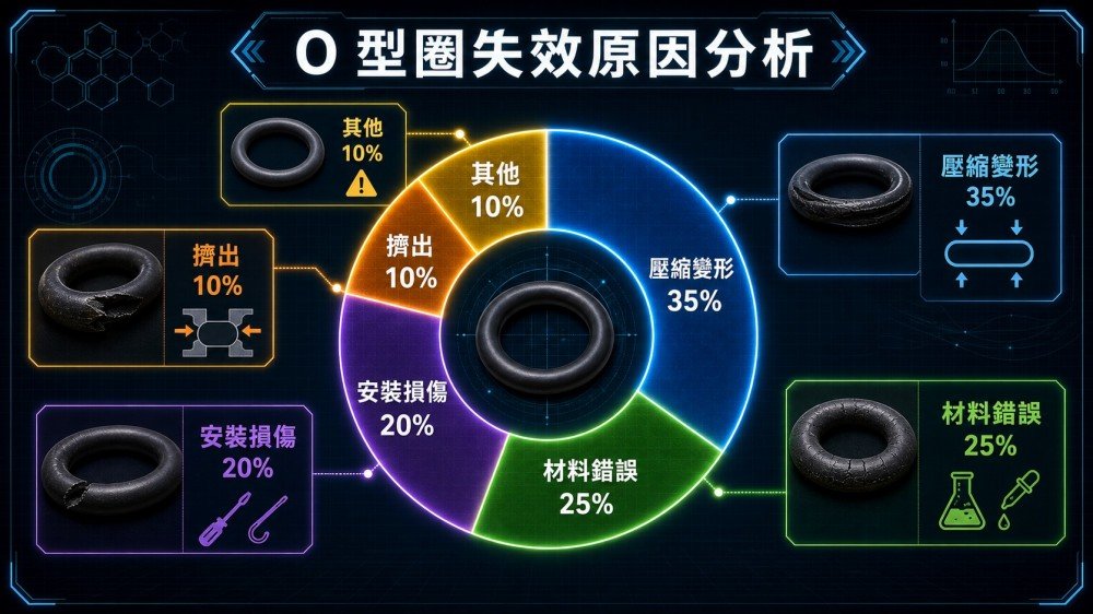
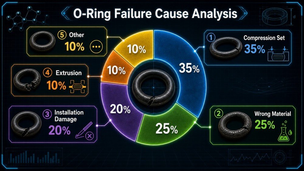
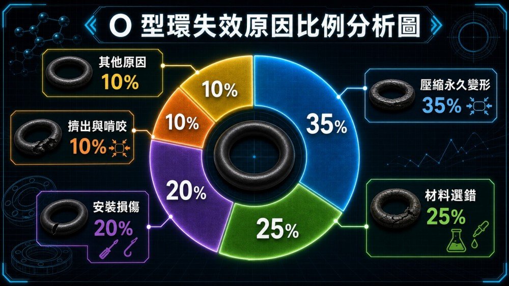
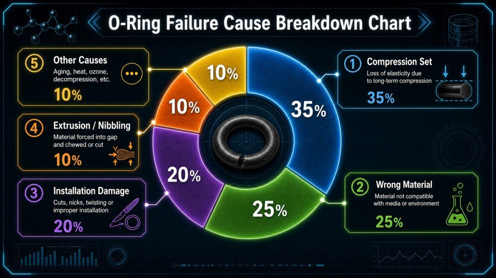
| Compression Set | O-rings have a flattened cross-section, have lost their circular shape, and no longer spring back. | Excessive compression ratio, excessive temperature, insufficient material hardness | Reduce the compression ratio to the recommended value; upgrade to high-temperature-resistant materials such as FKM or HNBR |
| Extrusion Failure (Extrusion) | There are burr-like protrusions along the edge of the O-ring, resembling notches made by a razor blade. | Excessive system pressure, excessive groove clearance, insufficient hardness | Install a backup ring; select an O-ring with a higher hardness (80–90 Shore A) |
| Spiral Failure | The surface of the O-ring features regular diagonal grooves, with alternating polished and matte sections around the entire circumference. | Insufficient lubrication in a dynamic reciprocating seal; continuous reciprocation after the cross-section is twisted | Increase the amount of lubricant; ensure that the cross-section is not distorted during installation; appropriately increase the groove width |
| Chemical Corrosion (Chemical Attack) | Bubble-like bulges appear on the surface of the O-ring, or it shows extensive dissolution and cracking, accompanied by abnormal swelling. | Material-medium incompatibility (e.g., NBR in contact with ketones, silicone in contact with mineral oil) | Verify material compatibility; upgrade to FKM or FFKM |
| Aging and Cracking (Thermal Degradation) | Fine cracks have appeared on the surface of the O-ring, which has become hard and brittle and breaks easily when bent. | Long-term operation in high-temperature environments, exceeding the material's temperature limit | Upgrade to FKM, which has higher heat resistance; verify that the actual operating temperature is within the material specifications. |
| Explosive Decompression | "Popcorn"-like pits and cracks have appeared on the surface of the O-ring, which has ruptured from the inside. | In gas systems, high-pressure gas penetrates the microporous structure of the O-ring; when pressure is rapidly released, the gas expands from within, causing the O-ring to burst. | Select materials with low permeability (such as HNBR or FFKM); control the pressure relief rate |
| Installation Damage | The surface of the O-ring has clean, sharp notches or neat slits. | Cuts caused by threads or sharp edges due to failure to use lubricant or protective sleeves during installation | Mandatory Installation SOP: Lubrication + Protective Sleeve + Deburring of Groove Edges |
| Abrasion Failure | One side of the O-ring’s contact surface shows flat wear, and the cross-section is no longer circular. | Excessive surface roughness in dynamic seals, or insufficient lubrication, can lead to direct metal-to-metal friction. | Improve the surface roughness of the groove contact surface (Ra ≤ 0.8 μm); increase the lubrication frequency |
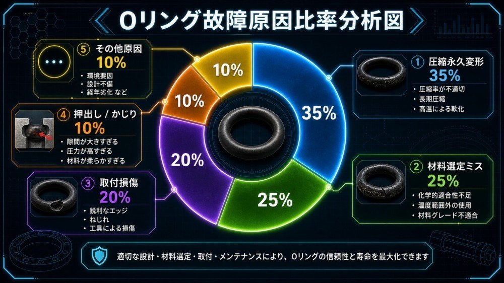
Pie Chart Showing the Proportion of Failure Causes

Chapter 6: Debunking O-Ring Myths: FAQ (10 Questions Total)
Q1: Can O-rings be reused?
In general, it is not recommended to reuse O-rings used in static seals after removal. Since they have remained in a state of plastic deformation within the groove for an extended period, their springback is typically insufficient to achieve the original sealing performance during a second installation. Dynamic seals, in particular, should be replaced regularly in accordance with the equipment’s maintenance schedule.
Q2: Are silicone O-rings oil-resistant?
Not resistant. This is the most widespread and dangerous misconception. Although silicone gives the impression of being “high-performance” in appearance and feel, it has extremely poor resistance to mineral oil, gasoline, and lubricating oil, and will rapidly swell and fail upon contact. For oil-resistant applications, choose NBR or FKM.
Q3: What is spiral failure?
This is a failure mode specific to dynamic reciprocating seals. During reciprocating motion, if the frictional force exceeds the O-ring’s own rotational resistance, the O-ring’s cross-section will move and rotate within the groove, eventually twisting into a “spiral” shape, which causes regular diagonal gouges to appear on the sealing surface. Difference from wear failure: The gouges caused by spiral failure appear as “alternating 45° diagonal cuts,” whereas wear results in “unilateral planar wear.”
Q4: What exactly is the difference between FFKM and FKM?
FKM (fluoroelastomer) has a fluorine content of approximately 66% and offers excellent chemical resistance; FFKM (perfluoroelastomer) has a fluorine content of 70% or higher and is resistant to virtually all chemical media (including ketones, esters, and strong oxidizing agents that FKM cannot withstand). FFKM is widely used in plasma etching chambers for semiconductor manufacturing processes, but its price is 10 to 100 times that of FKM; please do not upgrade unless absolutely necessary.
Q5: How is the compression ratio of an O-ring calculated?
Use the formula W = (d₀ – h) / d₀ × 100%, where d₀ is the cross-sectional diameter of the O-ring and h is the groove depth. The recommended range for static seals is 15% to 30%, and for dynamic reciprocating seals, it is 10% to 20%. A compression ratio below 10% results in insufficient sealing performance; a ratio above 30% significantly shortens service life.

Q6: NBR and EPDM look almost identical. How can you tell them apart?
The simplest method is the “oil immersion test”: Immerse the sample in engine oil for 24 hours, then remove it. If the volume has expanded significantly (>15%), it is EPDM; if the volume remains virtually unchanged, it is NBR. Burning test: When EPDM burns, the flame is white; when NBR burns, the flame is orange-red.
Q7: How can you prevent O-rings from being squeezed out under high pressure?
There are three methods: ① Install a backup ring, typically made of PTFE, on the low-pressure side of the O-ring to physically prevent the O-ring from being squeezed into the gap; ② Reduce the groove clearance (by tightening the fit tolerance); ③ Upgrade to a harder O-ring (80 or 90 Shore A).
Q8: If the O-ring is still leaking after installation, can I simply tighten it further?
No. In the case of a static flange face seal, “tightening it further” may cause the compression ratio to exceed the specified limit, which could actually accelerate compression set. The correct procedure is to first shut down the equipment and relieve pressure, then verify that the correct material was selected, the groove dimensions are standard, and the cross-section was not twisted during installation. After confirmation, replace the O-ring with a new one and retighten it according to specifications.
Q9: What special precautions should be taken with O-rings in low-temperature environments?
Standard rubber O-rings harden at low temperatures and lose their elasticity. The sealing performance of NBR drops significantly below -30°C, and that of FKM drops significantly below -20°C. In extremely low-temperature environments (such as liquefied natural gas (LNG) systems), silicone (which can withstand temperatures down to -50°C) or a special low-temperature FKM formulation should be used.
Q10: The specifications for my O-ring say “P-20 JIS B2401.” What does this mean?
This is the specification code for O-rings under the Japanese Industrial Standards (JIS). “P” stands for the “Packing” fit series (radial seals used for shaft diameter fits), and “20” represents the corresponding nominal shaft diameter (approximately 20 mm). In addition to the P series, JIS also includes the G series (general static fit) and the V series (for vacuum applications). When purchasing, ensure that the three numbers—the specification series, inner diameter (ID), and cross-sectional diameter (CS)—match exactly.
Conclusion: Choosing the right O-ring is the first step toward zero downtime in your facility.
Selecting the right O-ring is not something that can be accomplished simply by consulting a catalog; rather, it requires a systematic engineering approach that takes into account media compatibility, compression ratio design, SOPs for dynamic and static installation, and long-term failure prevention. We hope this guide will become one of the most frequently consulted references alongside your plant’s maintenance manual.
Still choosing materials based on intuition? We’ve prepared the “Four Major Material Compatibility Matrices” and the “Quick Reference Chart for Compression Ratio and Groove Depth” for engineers—available for download completely free of charge.