

When equipment begins to leak oil, water, or air, the old O-rings you have on hand, photos of the leak points, and maintenance records serve as the starting point for troubleshooting. By considering the dimensions, installation location, and operating conditions together, you can systematically identify the materials, parts, and assembly-related items that need to be verified.
Starting with used parts, this article guides you through verifying O-ring functionality, measuring dimensions, and identifying signs of leakage, before moving on to material selection, compression ratio, installation, and engineering validation. You can choose the order in which to read based on the information you have on hand, or you can use photos and equipment documentation in Chinese or Japanese to start a consultation covering materials, parts, and engineering through Chengxin’s LINE account.
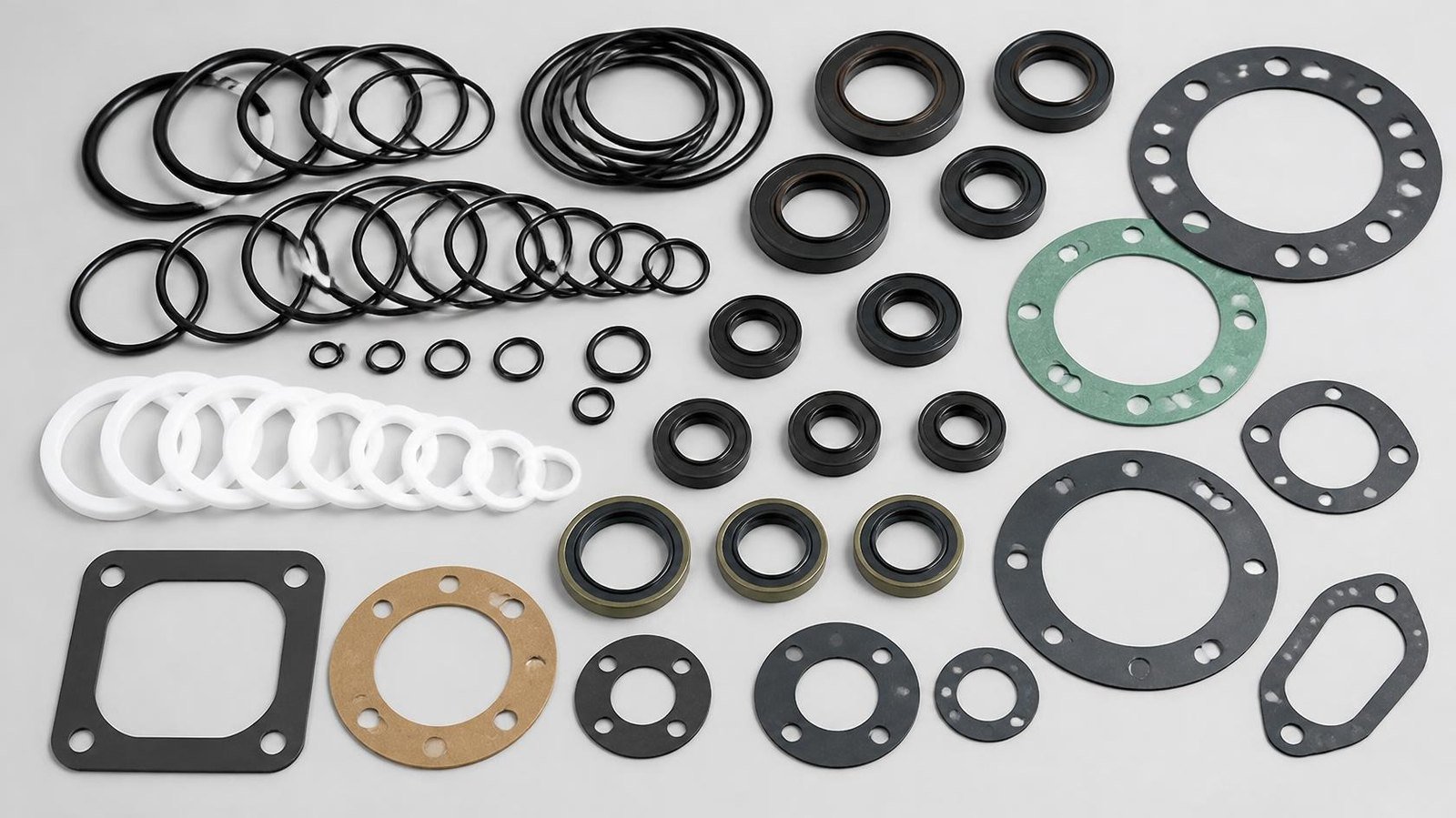
Various O-Ring Products
From standard O-rings and square rings to special sizes and material requirements, you can first review Chengxin’s O-ring and square ring products, then bring in your old parts, drawings, inner diameters, wire diameters, and operating conditions to discuss materials, dimensions, and manufacturing options.
View our selection of O-rings and square rings → |Send photos and specifications of the used item via LINE to start the consultation →
Chapter 1: How Do O-Rings Seal? First, Identify Their Function, Location, and When Leaks Occur
1-1 What Is an O-Ring? Understanding Its Function Through Its Cross-Section and Sealing Position
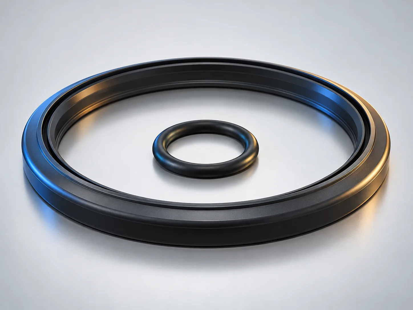
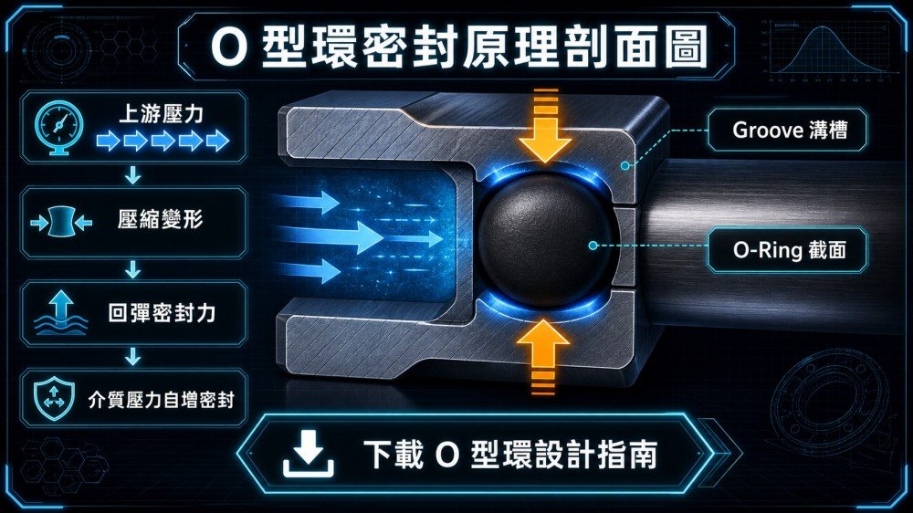
An O-ring is a ring-shaped seal with a circular cross-section that is typically installed in a groove; it forms a seal with the contact surface through compression during assembly. System pressure also pushes the seal against the mating surface. Sealing performance depends on a combination of factors, including the material, wire diameter, groove, clearance, and operating conditions.
1-2 Static and Dynamic Seals: Documenting the Equipment's Motion Patterns
First, determine the location of the O-ring: If it maintains a fixed position between mating surfaces, it is a static seal; if there is relative motion between mating components such as the piston and piston rod, it is a dynamic seal. The nature of the motion affects groove design, friction, lubrication, and material selection; therefore, “where it is installed” is a critical piece of information for determining specifications.
A comprehensive view of the filming equipment, its installation location, and the trench after dismantling helps connect the parts to the equipment’s structure, making subsequent discussions more concrete.
1-3 When Do Leaks Occur? A Summary of Phenomena During Shutdown, Startup, and Operation
Divide the timing of leaks into the following stages: installation completion, startup and pressurization, warm-up and operation, and after a period of use; then record the medium, temperature, pressure, and replacement date. Parker’s seal failure analysis also lists hardware, installation method, operating conditions, and time of failure as diagnostic data.
| On-site Data | Suggested Content for the Record |
|---|---|
| Installation Location | Equipment Name, Joint Surface, or Moving Part |
| Terms of Use | Medium, Temperature, Pressure, and Mode of Motion |
| Leakage Records | When the Problem Occurred, Location of the Leak, and the Replacement Process |
Chapter 2: How to Match Parts When You Only Have an Old O-Ring? From Measurement to Confirming Specifications for a New Part
2-1 Inner Diameter, Outer Diameter, and Wire Diameter: Confirming Measurement Locations and Recording Methods
To determine the size of an O-ring, first understand the inner diameter, outer diameter, and wire diameter. The inner diameter is the diameter of the inside of the ring; the outer diameter is the diameter of the outside of the ring; and the wire diameter is the diameter of the circular cross-section, which is a dimension closely related to the groove compression.
For a free-form ring with a complete shape and uniform cross-section, the geometric relationships between its dimensions can be verified using the following equation:
Outer Diameter = Inner Diameter + 2 × Wire Diameter
The "2" in the equation represents one cross-section on each side of the diameter. This relationship is suitable for verifying records; the dimensions of used parts should be interpreted in conjunction with post-use changes and data on mating parts.
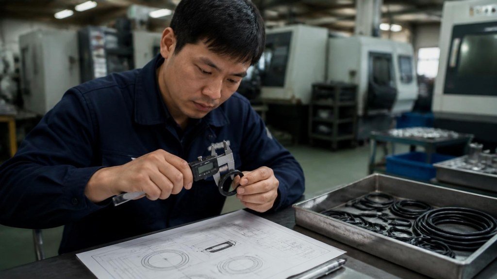
When taking measurements, allow the ring to rest naturally on a flat surface, record the readings with light contact, and note the readings from different directions. When taking photographs, place the ruler and the measurement area on the same plane so that the photo clearly shows the dimensions, location, and tool readings.
2-2 If the old part has hardened or warped, verify the dimensions by checking the keyway and the mating part.
Used seals have been subjected to compression, temperature, and the effects of the medium; after removal, they may exhibit a flattened cross-section or changes in volume and elasticity. Parker lists compression set, media compatibility, and temperature exposure as key factors in failure analysis; therefore, measurements taken from the old part serve as suitable current condition data for cross-verification against the original specifications.
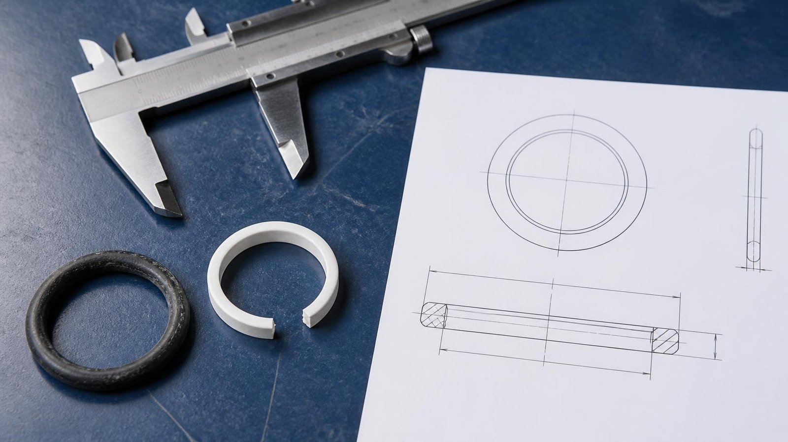
In practice, old parts, grooves, and mating components can be organized into a single set of data: the old parts provide information on appearance and current dimensions; the grooves provide installation space; and the mating components and drawings provide the design basis. Retaining material labels, part numbers, and maintenance records also helps in verifying the original specifications.
2-3 Metric, Imperial, and JIS Markings: Compilation of Specification Series and Dimension Data
Equipment documentation may follow different specification series. When organizing this information, record the “original designation, unit of measurement, inner diameter, wire diameter, material, and part number” in separate columns, and verify tolerances against the corresponding standards or supplier dimension tables. Parker manuals provide dimension, groove, and tolerance data and can serve as a technical reference for specification verification.
| Source | Priority Content |
|---|---|
| Used Items and Packaging | Measurement values, labels, part numbers, photos of the product's appearance |
| Equipment Drawings | Specification Series, Dimensions, Tolerances, and Material Requirements |
| Grooves and Mating Parts | Groove width, groove depth, fit dimensions, and surface condition |
2-4 How Are Approximate Dimensions Evaluated? A Checklist Before Establishing a Substitute
Once you have found a size that is close to what you need, next verify the wire diameter, installation elongation, compression, groove clearance, and material conditions. The Parker manual notes that installation elongation alters the cross-sectional dimensions, and groove design should account for this change when evaluating compression.
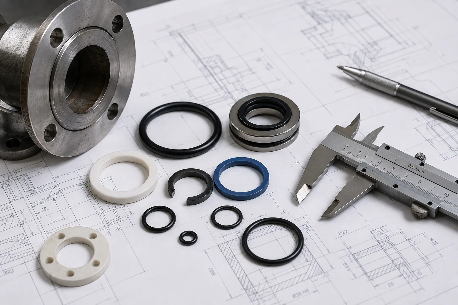
Therefore, the substitution verification process can be carried out in the following sequence: “Dimensions and Tolerances → Grooves and Clearances → Materials and Operating Conditions → Assembly and Verification.” By comparing the candidate specifications side-by-side with the original documentation, differences and verification items can be clearly organized, ensuring that both procurement and on-site operations are based on the same set of data.
Chapter 3: How to Establish a Troubleshooting Sequence When a Leak Persists After Replacing an O-Ring?
3-1 Classification by Time of Leakage: After installation, after heating, and after a period of operation
If a leak persists after a replacement, you can establish an initial troubleshooting sequence based on “when the leak began.” For leaks that occur immediately after installation, first review the dimensions, seating condition, contact surfaces, and assembly process; for leaks that occur after heating or pressurization, factor in temperature and pressure changes, material conditions, and clearance during the assessment; For leaks that occur after a period of operation, analyze them in conjunction with factors such as wear, compression set, and the effects of the working medium.
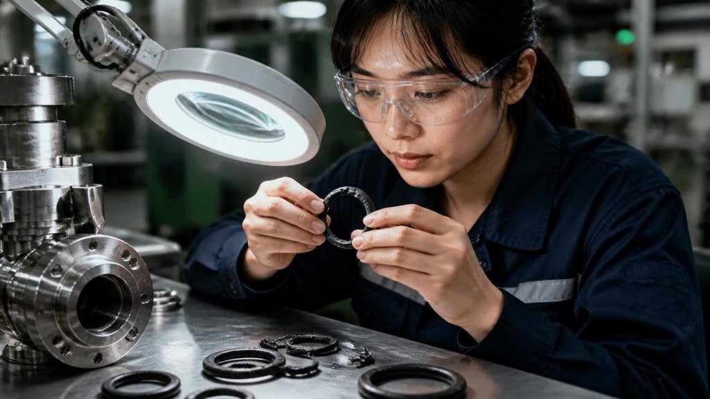
These sorting categories provide guidance for inspection; the ultimate cause is determined based on a combination of appearance, dimensions, operating conditions, and verification results.
3-2 Gathering Clues from the Appearance of the Old Ring: Flattening, Cracks, Notches, and Wear
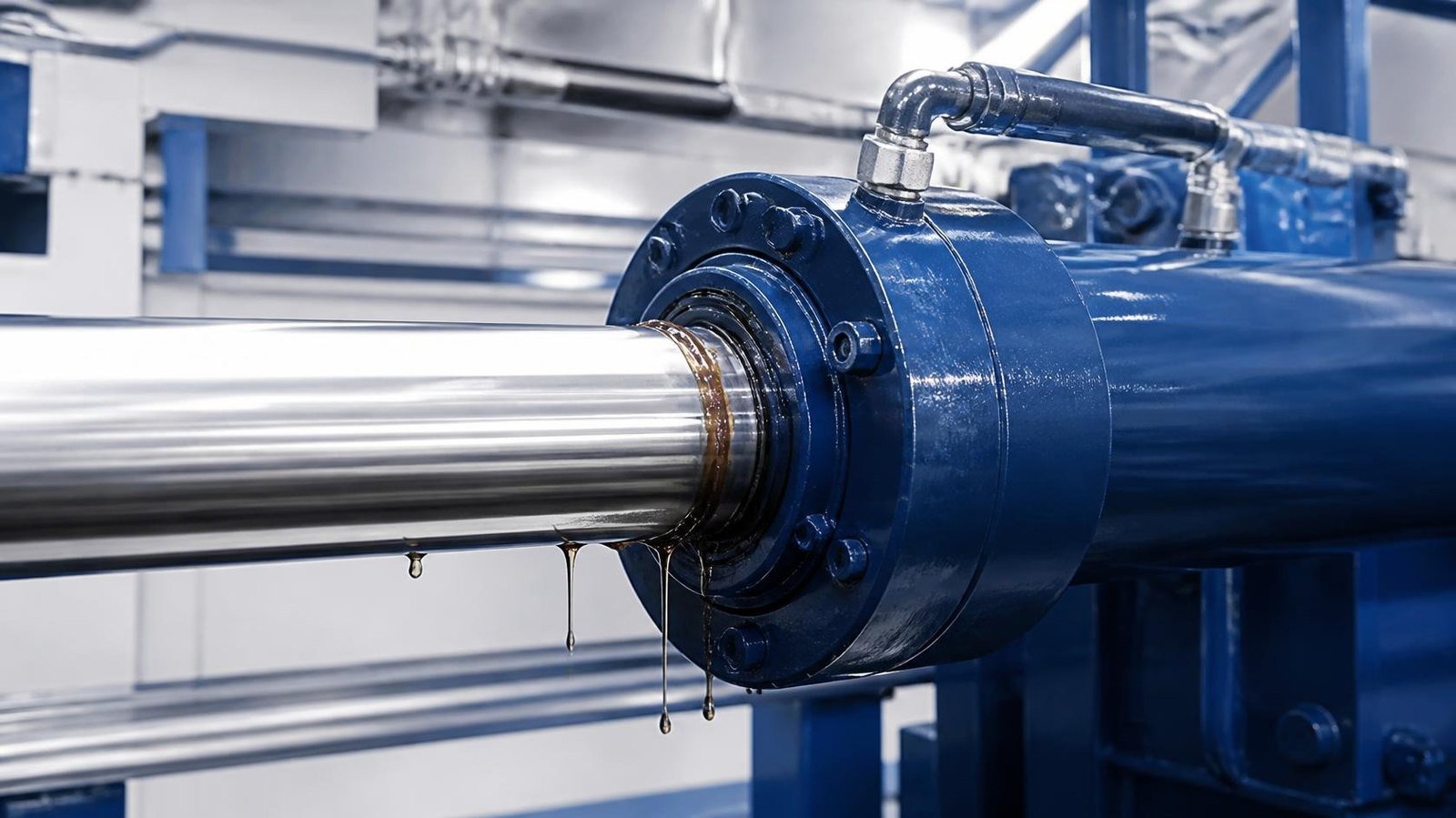
Keep the old ring that was removed, mark its installation orientation and the location under pressure, and then take both full-view and close-up photos. Parker points out that seal failure may result from a combination of multiple mechanisms, and a complete understanding of the operating conditions can help identify the underlying causes behind the visible symptoms.
| Visual Clues | Expandable Confirmation Directions |
|---|---|
| Flat cross-section, altered recovery capacity | Compression Set, Temperature, Materials, and Groove Conditions |
| Edge notches, localized extrusion marks | Pressure, Clearance, Material Hardness, and Anti-Extrusion Design |
| Localized dents and scratches | Assembly Paths, Threads, Sharp Edges, and Lead-In Protection |
| Scuff marks or spiral-shaped marks | Motion, Lubrication, Surface Condition, Eccentricity, and Lateral Loads |
The above guidelines are based on the Parker manual and failure analysis; when making an actual assessment, compare the location of the marks with the equipment’s structure.
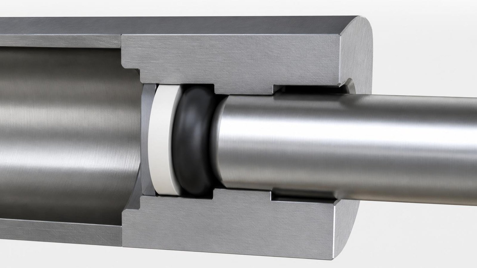
3-3 Relate the clues back to the materials, dimensions, grooves, and installation conditions
The inspection can be organized into four sets of data. The Materials group verifies the grade, medium, and temperature; the Dimensions group checks the inner diameter, wire diameter, and tolerances; the Grooves group verifies the groove depth, groove width, and fit clearance; and the Installation group records the lubrication, insertion, and positioning status.
The compression ratio is also verified during this stage: in terms of the geometric concept of simple cross-sectional compression, the compression ratio is the percentage obtained by dividing “the difference between the wire diameter and the effective sealing space height by the wire diameter.” The formal evaluation then compares this value with applicable design data, taking into account the seal configuration, dimensional tolerances, and assembly elongation.
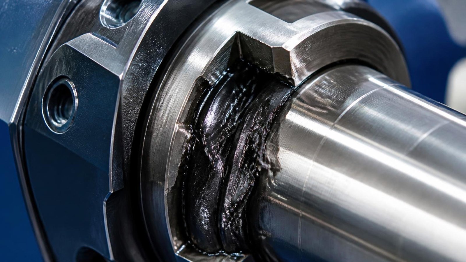
For example, notches can be linked to pressure and clearance; indentations can be linked to assembly paths; and flattened areas can be linked to material, temperature, and groove conditions. This allows current failure diagnosis information to be converted into a field checklist with items that can be verified one by one.
3-4 Establish a record of verification for confirmed items and improvements
Map each improvement to the “original condition, adjustment details, verification conditions, and results,” and retain before-and-after photos as well as parts data. Conduct verification in accordance with the applicable procedures for the equipment, and document the medium, temperature, pressure, operating status, and observation period to ensure the results are based on clearly defined conditions.
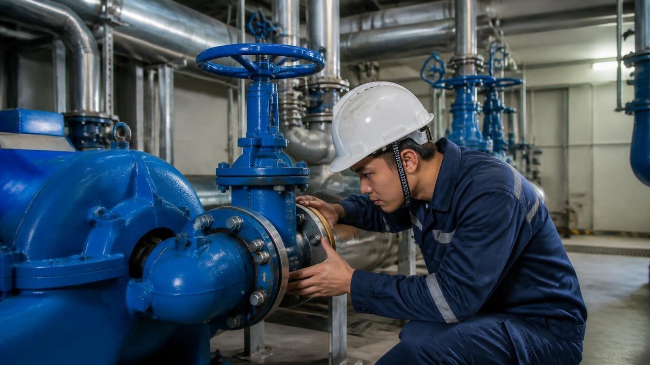
Disassembly and inspection procedures are carried out in accordance with equipment shutdown, power isolation, and pressure relief protocols; the completed records can also serve as a common reference for discussions regarding materials, parts, and subsequent engineering work.
Chapter 4: How to Select Materials and Grooves Together? Integrating the Medium, Temperature, Pressure, and Compression Ratio
4-1 First, identify the operating conditions: medium, concentration, and normal and peak temperatures and pressures
When selecting O-rings, start by identifying the media with which the equipment actually comes into contact. Compile the names, concentrations, and product specifications of oils, cleaning solutions, or process fluids, and then add the normal temperature, peak temperature, pressure, and operating cycles. This will ensure that the material comparison is more closely aligned with actual field conditions. Material compatibility should also account for substances encountered during cleaning, storage during downtime, and lubrication.
When recording temperature, also indicate the measurement location, duration, and cycle conditions; when recording pressure, include the methods used for pressurization, pressure holding, and depressurization. These conditions, together with material properties, seal clearances, and assembly conditions, collectively affect performance.
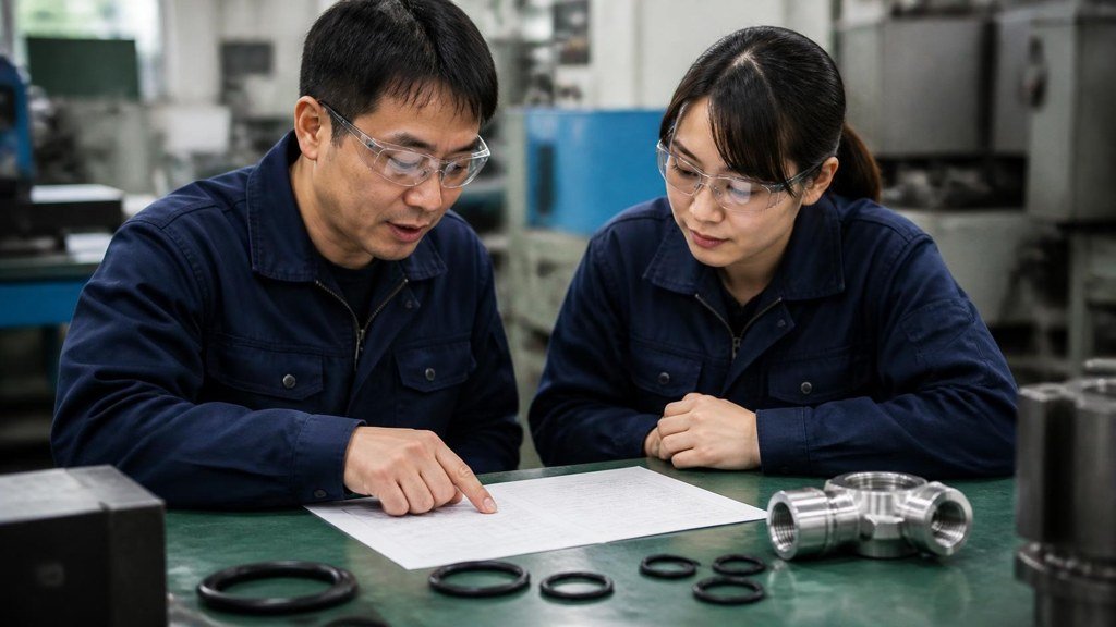
4-2 Comparison of NBR, EPDM, FKM, Silicone, HNBR, and FFKM
The material name serves as a starting point for selection; suitability should then be confirmed based on the actual formulation, hardness, medium, and temperature. The following provides a preliminary comparison of common materials; official specifications are based on the data and validation results for the selected material grade.
| Materials | Preliminary Assessment Directions | Further Clarification of Key Points |
|---|---|---|
| NBR Nitrile Rubber | Mineral Oil, General Hydraulic and Pneumatic Seals | Oil Additives, Temperature, and Weather Resistance Requirements |
| EPDM EPDM Rubber | Water, some steam, and the outdoor environment | Water Quality, Cleaning Solutions, Lubricants, and Media Compatibility |
| FKM Fluoroelastomer | High-temperature oils, fuels, and various chemical media | Specific Chemicals, Low-Temperature Conditions, and Material Grades |
| Silicone/VMQ Silicone Rubber | Static seals in areas subject to significant temperature fluctuations | Tearing, Abrasion, Gas Permeation, and Service Conditions |
| HNBR (Hydrogenated Nitrile Rubber) | Balancing lubrication, mechanical strength, and heat resistance requirements | Formulations, Operating Conditions, and Media Compatibility |
| FFKM Perfluoroelastomer | High-Precision Chemical, Thermal, and Cleanroom Processes | Application-Specific Grades, Process Media, Documentation, and Validation Requirements |
The above is a comparison at the material family level, compiled based on Parker’s material and application data.
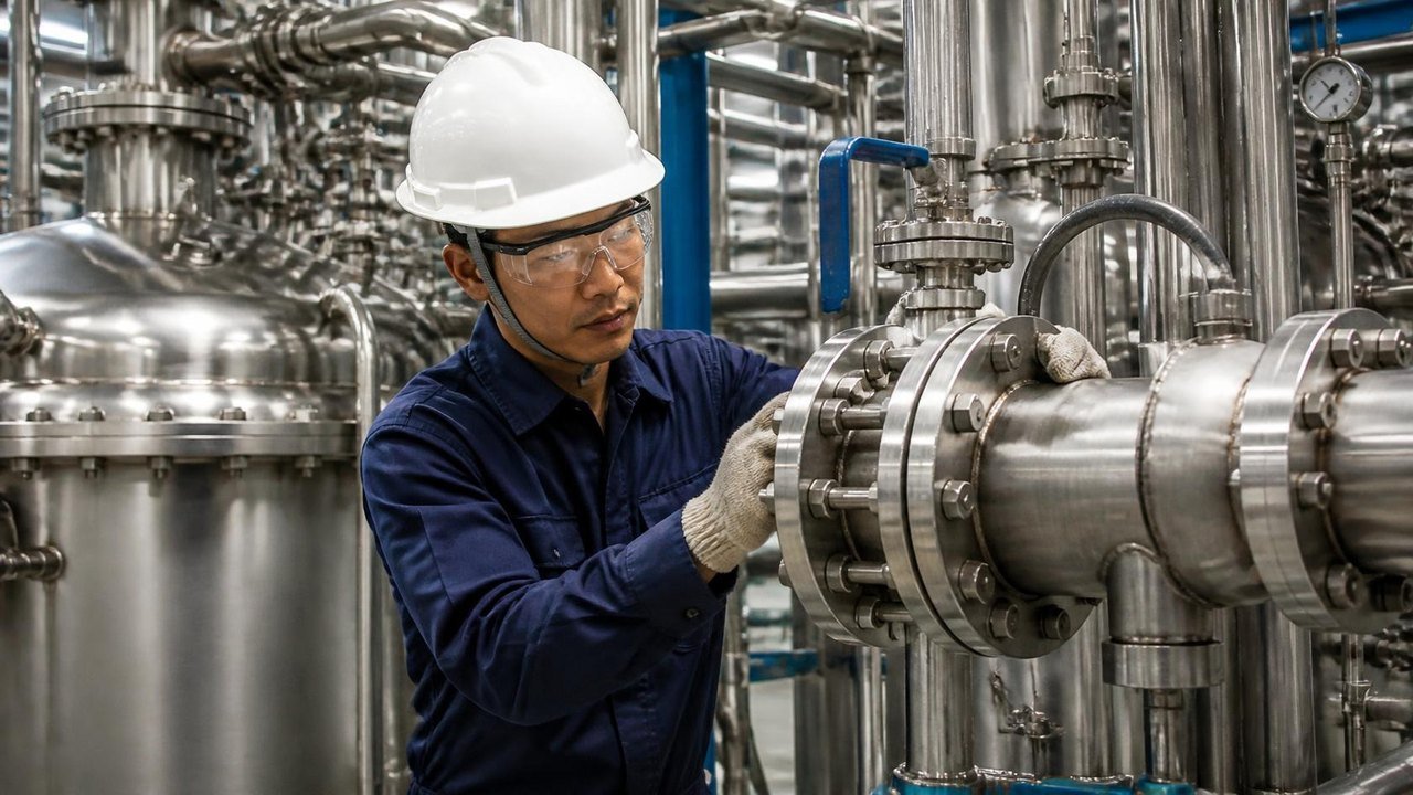
4-3 How is the compression ratio calculated? Refer to wire gauge, grooves, and applicable conditions
The compression ratio describes the proportion of the O-ring cross-section that is compressed after assembly. It is represented using a simplified cross-sectional model as follows:
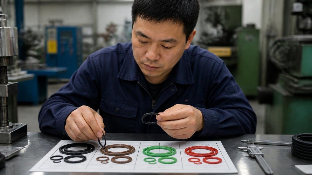
Compression Ratio = (d − h) / d × 100%
Here, d represents the wire diameter used in the evaluation, and h represents the effective sealing space height for that seal configuration; both are expressed in the same unit of length. The formal design must account for the wire diameter, part tolerances, assembly elongation, and temperature effects, and the design data must be cross-referenced based on whether the application is static or dynamic.
4-4 Confirm material grades and dimensional tolerances along with the equipment documentation
After completing the preliminary material selection, list the material grade, hardness, dimensional tolerances, groove width, groove depth, and fit clearance on a single confirmation sheet. The compression amount, groove volume, and clearance together constitute the design conditions, which are suitable for a comprehensive review; verification should then be arranged according to equipment requirements.
Chapter 5: How to Install and Verify O-Rings? Establishing Records of Replacement Operations
5-1 Before Installation: Check the condition of the parts, grooves, and contact surfaces
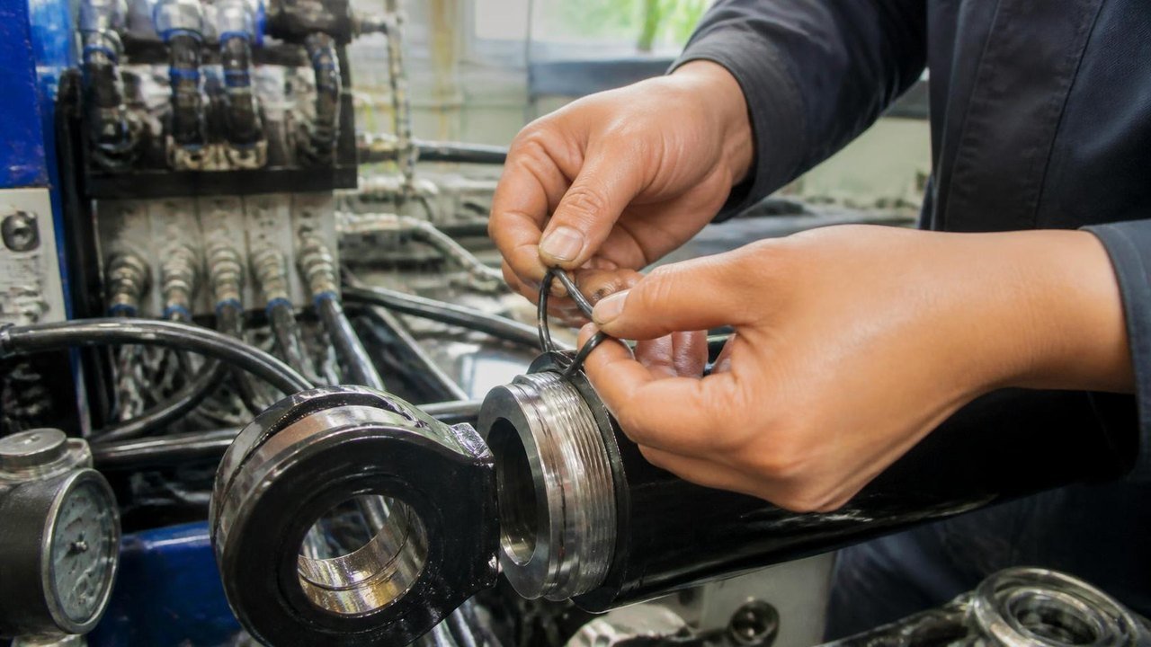
Before replacing a part, first follow the equipment procedures to shut down the system, isolate the power supply, and relieve pressure. Then, verify the part number, dimensions, material, and condition of the new part. When removing the old part, note its orientation and position; clean and inspect the grooves and contact surfaces; and take photographs of any scratches, burrs, or signs of wear for record-keeping purposes.
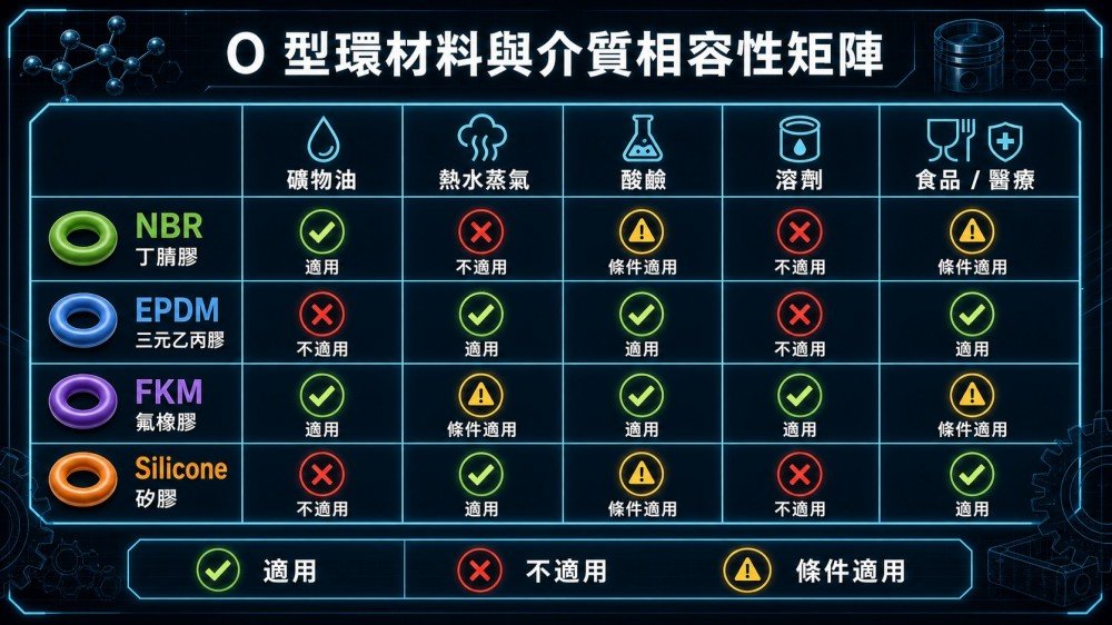
The surface of the groove, the guide structure, and the sealing clearance all affect assembly and operational performance; incorporating the inspection results into the equipment drawings helps identify items requiring follow-up action.
5-2 During Installation: Verify Lubricant Compatibility, Implementation of Protective Measures, and Positioning Status
The lubricant must be compatible with the O-ring material, the working fluid, and the equipment application. Parker lists elastomer compatibility, operating temperature, lubricant film retention capability, and system fluid compatibility as selection criteria, which can be used to create a field verification checklist.
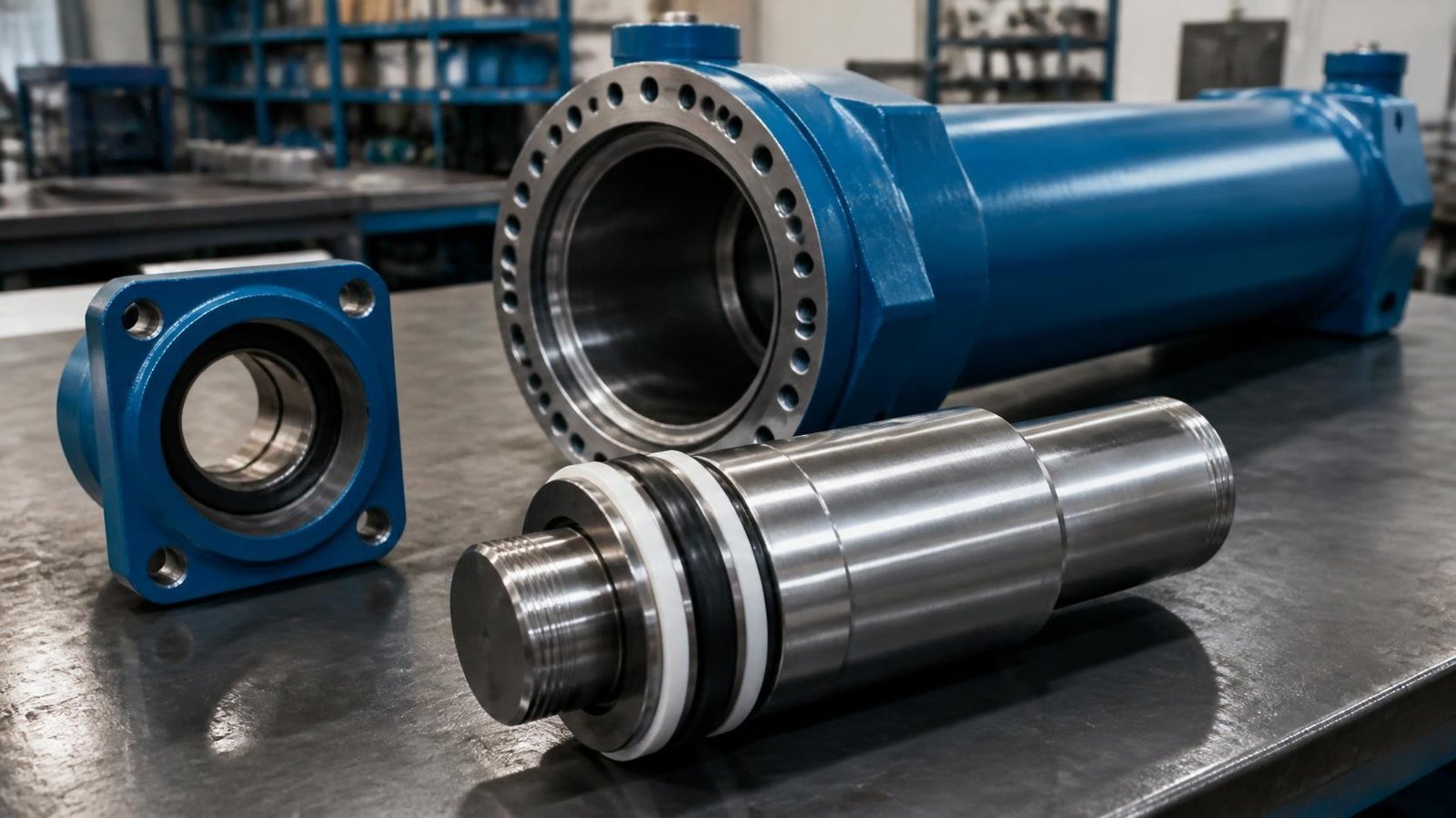
When passing through threads, orifices, or steps, use guide sleeves and protective tools as specified in the assembly design to ensure the ring passes through smoothly. Once in position, verify the circumferential alignment, the position of mating parts, and the completion of the assembly, then complete the fastening or assembly in accordance with equipment specifications.
5-3 After Installation: Record the sealing and operating conditions in accordance with the equipment procedures
Restart and testing procedures are conducted in accordance with the applicable equipment procedures, and the test medium, temperature, pressure, operational status, and observation time are all recorded. If there are any changes to the materials, dimensions, or lubrication methods, these are also noted in the records to provide a consistent baseline for subsequent tracking.
| Session | It is recommended that the record be retained. |
|---|---|
| Before Installation | Information on new and old parts, along with photos of grooves and contact surfaces |
| Installing... | Lubricants, Application Methods, and Verification of Proper Positioning |
| After installation | Test Conditions, Operating Conditions, and Observations |
This record converts replacement operations into traceable data, helping engineering, maintenance, and procurement teams share the same specifications and on-site information.
Chapter 6: How Does Chengxin Assist with Verification? Taiwanese-Japanese Bilingual Consultations Integrating Materials, Parts, and Engineering
6-1 Start with Old Documents and Photos: Organizing Materials from the First Round of Consultations
Existing equipment, photos of leaks, packaging labels, and maintenance records can all serve as a starting point for our discussion. Begin by providing the equipment’s intended use, installation location, medium, and temperature and pressure conditions; then add the dimensions and groove specifications to gradually establish the specifications.
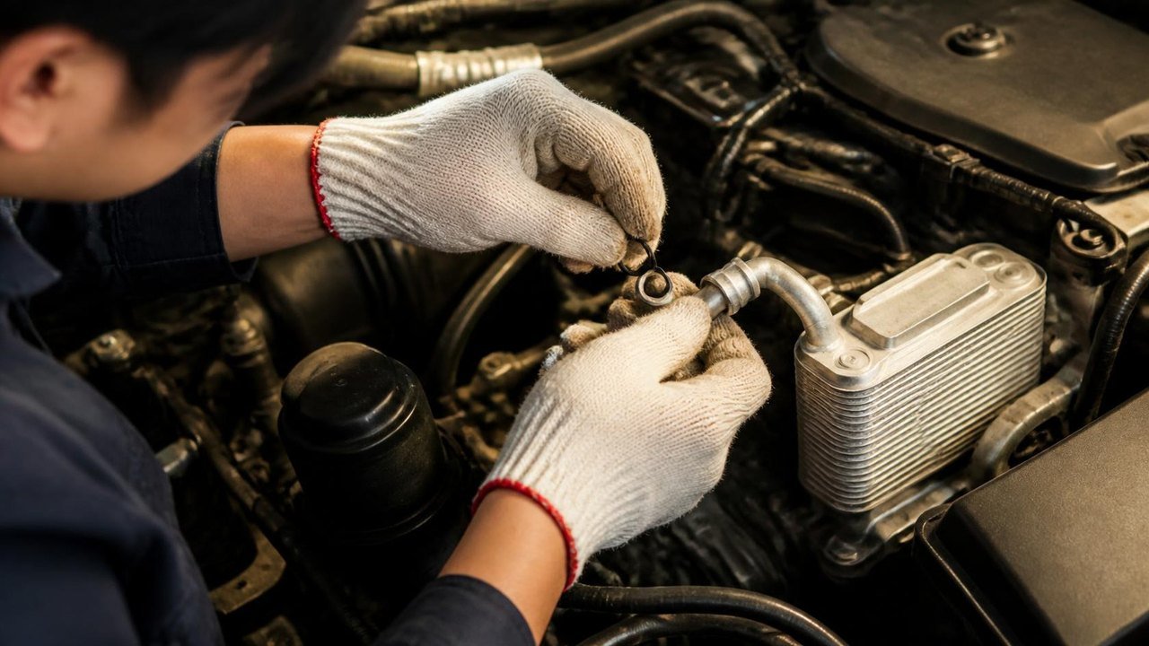
Photos can be organized by showing the overall view of the equipment, its installation location, the overall view of the old ring, and close-ups of specific details; photos showing dimensions should include a ruler or measuring tape so that the measurement location and readings are displayed together.
6-2 Materials, Dimensions, Part Fabrication, and Engineering Verification Items for Series Connection
Taking an integrated approach that combines materials, parts, and engineering, Chengxin organizes on-site information into interconnected verification items: materials correspond to media and temperature; parts correspond to dimensions and tolerances; and engineering links together grooving, assembly, and verification conditions.
6-3 Taiwanese-Japanese Bilingual Comparison: Integration of Equipment Names, Specifications, and Operating Conditions
When working with Japanese equipment drawings, you may retain the original Japanese labels and supplement them with Chinese notes describing the on-site conditions, so that both technical specifications and practical experience can be incorporated into the discussion.
| Chinese Materials | Japanese Translation |
|---|---|
| Medium/Fluid | Fluid |
| Temperature/Pressure | Temperature/Pressure |
| Inner Diameter / Wire Diameter | Inner Diameter / Wire Diameter |
| Groove Dimensions | Groove Dimensions |
| Location of the Leak | Omissions |
Chapter 7: O-Ring FAQs—From On-Site Questions to Specification Confirmation
Q1: What is the function of an O-ring? Where is it typically used in equipment?
O-rings create a seal between mating surfaces through compression during assembly and under system pressure; they are commonly used in joint surfaces, valve bodies, and areas subject to reciprocating motion. When determining their application, documenting both the sealing location and the type of motion can assist in subsequent material selection and groove evaluation.
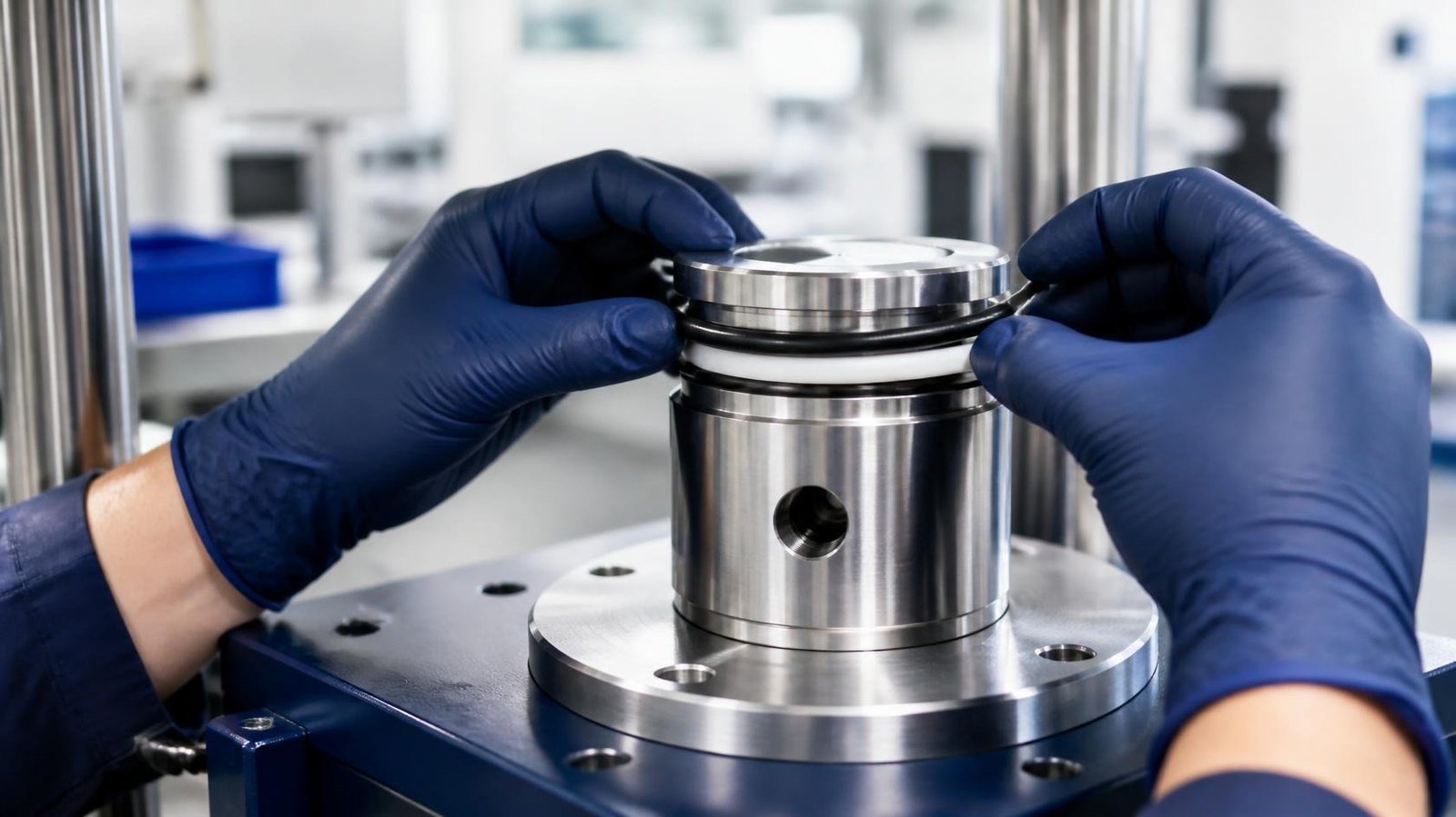
Q2: Japanese drawings use the terms “O-ring” and “packing.” What is the difference between the two?
An O-ring refers to a ring-shaped seal with a circular cross-section; the term “packing” may refer to various types of sealing components in equipment documentation. Actual identification is based on the cross-sectional view in the drawings, part numbers, installation locations, and the equipment parts list. The original names are retained to facilitate cross-referencing between Chinese and Japanese documentation.

Q3: How much do O-rings cost? What information do I need to provide when requesting a quote?
Price estimates can be based on dimensions, material grades, quantities, manufacturing requirements, inspection documentation, and delivery terms. When requesting a quote, please provide the inner diameter, wire diameter, intended use, and estimated quantity. If you have existing parts or drawings on hand, please include them as well so that the quote can be based on specific specifications.
Q4: What are some well-known O-ring manufacturers in Taiwan? How should I choose who to consult?
When selecting a consultation partner, evaluate factors such as availability of sizes, material specifications, batch traceability, inspection documentation, customization support, and engineering communication capabilities based on your needs. For the procurement of standard parts, the focus is on specifications and delivery; for equipment issues, factors such as grooves, operating conditions, and validation support are also considered to ensure that service terms align with on-site tasks.
Q5: Are O-rings heat-resistant? Should I specify the normal temperature or the maximum temperature?
Temperature resistance depends on the material formulation, the medium with which it comes into contact, and the exposure conditions. Providing the normal temperature, peak temperature, duration, and cycling pattern during consultation, and then evaluating these factors based on the data for the selected material grade, will ensure that the temperature resistance verification more closely reflects actual operating conditions.
Q6: How do I choose the right O-ring size? I only have an old, used O-ring on hand.
First, record the inner diameter, wire diameter, and appearance of the old ring, then add details regarding grooves, mating parts, and equipment part numbers. Any deformation resulting from use can serve as a clue to its current condition; specifications for new parts should be verified by referring to dimension tables, tolerances, and installation space, allowing the data from the old part to be aligned with the equipment’s requirements.

Q7: The O-ring has been replaced, but the equipment is still leaking. Where should I check first?
First, record the time and location of the leak, then document the appearance, dimensions, and material of the old O-ring, as well as the replacement process. Next, systematically check the grooves, clearance, medium, and assembly conditions, listing the verified items alongside the test results to gradually narrow down the scope of the investigation.
Q8: If I find an O-ring with very similar dimensions, how do I verify that it is a suitable replacement?
List the inner diameter, wire diameter, tolerances, and material of the candidate parts alongside the original specifications, then verify the assembly elongation, compression, and groove clearance. Parts with dimensions that are close to the original specifications can serve as starting candidates; whether to adopt them as replacements should be confirmed based on equipment conditions and validation results.
Q9: What lubricant should be used when installing O-rings? What product information is required?
Provide the complete product name, technical data, working medium, and O-ring material grade of the lubricant, then verify compatibility and operating temperature. For food, cleanroom, or special process applications, also include relevant specifications and documentation in the verification process to ensure that the lubrication method meets the equipment requirements.
Q10: I have photos of the old parts and drawings of the Japanese equipment. Can I consult with you via LINE?
You can begin by organizing old parts, photographs, and Japanese equipment drawings. By providing installation locations, measurement data, media types, and temperature and pressure specifications—while retaining the original part numbers and terminology on the drawings—you can use bilingual (Taiwanese and Japanese) data to link materials, dimensions, and engineering verification procedures.
Conclusion: Based on previous cases and overlooked issues, compile O-ring-related problems into engineering verification documentation.
The dimensions, materials, grooves, and installation conditions of O-rings are all interrelated. By starting with the old parts and leak points and gradually adding information on the medium, temperature, pressure, equipment location, and replacement records, you can ensure that every assessment is based on on-site data.

When preparing materials for the consultation, you can use this checklist to organize them:
Photos showing the overall view, close-ups, and areas with leaks of the old ring.
Information on inner diameters, wire diameters, grooves, and mating parts.
Medium, normal, and peak temperature and pressure.
The timing of the leak, the repair process, and the equipment documentation.
Using an integrated approach that combines materials, parts, and engineering, Chengxin works with you to organize on-site information into specifications and verification items, ensuring that product selection, procurement, assembly, and validation all follow a single workflow.